


Core pins are small components inside a die casting tooling. They create the holes, slots, and internal cavities that define a part’s function, and their geometry, material, and placement affect fill behavior, ejection reliability, dimensional accuracy, and tool longevity across every production run.
This blog will cover how core pin design connects to alloy selection, cooling strategy, failure modes, and inspection workflows, giving design and manufacturing teams a practical reference for tooling decisions that hold up under high-volume production.
What Core Pins Do In Die Casting Tools
Core pins shape internal part geometry that cannot be formed by the die cavity alone. In aluminum molds and other die casting tooling, their placement, size, and support conditions determine whether features come out clean and consistent or become a recurring source of scrap and downtime.
How Pins Form Internal Features
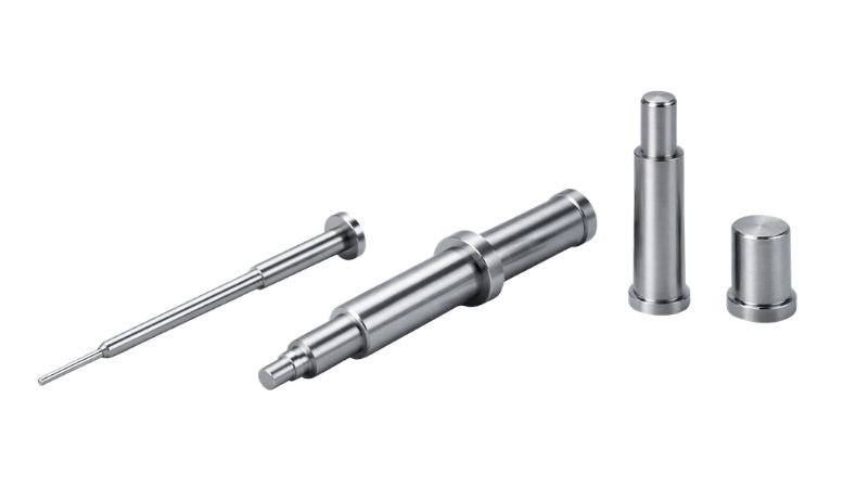
A core pin is a separate, replaceable insert positioned inside the die that displaces molten metal during injection, leaving behind a hole, boss, channel, or hollow section. This approach handles geometries like threaded holes or deep blind bores that would be impossible to machine directly into the die face. Separate core pins are used because deep features are difficult to machine directly into the die block, and replaceable pins significantly lower maintenance costs when wear or breakage occurs.
Interaction With Ejection
Core pins can be fixed to the stationary or moving half of the die, mounted in slides, or driven hydraulically. During ejection, pins must clear the part cleanly. Misalignment between a core pin and an ejector pin operating nearby creates binding, marks the casting surface, or bends the pin under side load.
Design Factors That Shape Core Pin Performance
Pin design involves more than selecting a diameter and length. Geometry, alloy, and thermal behavior all interact, and getting one wrong creates problems that look like process issues but trace back to the tooling drawing.
Geometry and L/D Ratio
The length-to-diameter (L/D) ratio is the single most important geometric constraint. Long, thin pins deflect under injection pressure, and at high L/D ratios, that deflection becomes permanent bending or sudden breakage. As a practical guide, L/D ratios above 6:1 require additional support strategies such as guided bushings, increased pin diameter, or reduced fill velocity.
Draft, Venting, and Fill Behavior
Draft on a core pin (typically 0.5 to 1.0 degrees) reduces ejection force and allows the casting to release. Metal flow around a pin creates a weld line where two flow fronts meet; mold flow analysis can confirm whether the weld line location is acceptable before cutting steel. Venting near pin features prevents trapped air from creating porosity, and small vent slots can serve this function when positioned deliberately in the die design.
Alloy-Specific Adjustments
Aluminum is injected at high velocity and temperature, requiring pins with higher hardness, erosion-resistant coatings, and internal cooling. Zinc runs at lower temperatures, reducing thermal shock, but its tendency to solder makes pin surface finish critical. Magnesium alloys are lighter but run at elevated temperatures; thin-walled parts often require narrow pins, pushing L/D ratios higher and making support design vital.
Materials, Hardness, And Surface Engineering Choices
The choice of steel, heat treatment, and surface coating determines how long the pin performs and whether soldering or erosion becomes a recurring issue. Material suppliers publish specific configurations reflecting how much material selection influences tool life.
Tool Steels And Heat Resistance
H13 tool steel is the most widely used material for core pins, offering a balanced combination of hot hardness, thermal fatigue resistance, and toughness that suits aluminum and zinc applications well. Hardness targets typically fall between 44 and 52 HRC. Heat treatment uniformity matters as much as the target hardness value; inconsistent through-hardening leaves a pin vulnerable to failure.
Cooling and Specialty Designs
Standard solid core pins accumulate heat over successive shots, increasing soldering risk. Cooling core pins use an internal tube or drilled passage to circulate water or oil, extending pin life in demanding applications. Specialty pins using beryllium copper inserts improve heat transfer in sections where water cooling channels cannot reach.
Coatings And Surface Treatment
PVD coatings (CrN, TiAlN, AlCrN) improve surface hardness, reduce friction, and create a barrier against soldering and erosion. Nitriding adds a hardened diffusion layer that improves wear resistance, performing well in zinc and moderate aluminum applications.
Common Failure Modes And Preventive Maintenance
Recognizing how and why pins fail allows engineering and maintenance teams to build schedules and process controls that keep production stable.
Breakage, Erosion, And Thermal Fatigue
Pin breakage occurs when bending stress exceeds tensile strength. This is often exacerbated by poor alignment; as guide pillars wear, pin alignment shifts, redirecting injection pressure into lateral load on the pin shank. These factors combined can make a tool unmaintainable at production volumes. Furthermore, erosion results from high-velocity metal washing the pin surface away, while thermal fatigue creates heat checking from repeated rapid heating and cooling.
Preventive Maintenance Planning
Reactive maintenance is expensive. Tracking pin condition at each scheduled die inspection—measuring retention fit, surface condition, and straightness—gives the team the data needed to set planned replacement intervals before failure occurs.
Inspection, Tolerances, And Quality Control
Dimensional control on cast features formed by core pins requires confirming both the pin’s condition and the accuracy of the geometry it creates.
Dimensional Checks
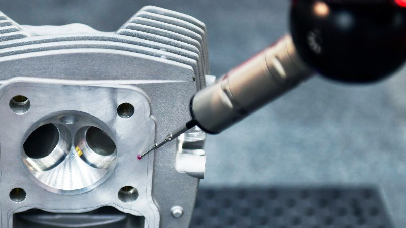
Core pin diameter, roundness, and length must be verified regularly. An eroded pin can push the resulting hole diameter outside the tolerance band specified by the customer. First article inspection should confirm pin-formed features against the part drawing using calibrated gauges or CMM data before production release.
Advanced Validation (CMM & X-Ray)
Coordinate measuring machines (CMM) verify hole position and diameter. X-ray inspection is specifically useful for detecting shrinkage porosity in the wall sections adjacent to a pin feature. Assessing a supplier’s tooling capability involves a proper tool validation sequence, including initial dimensional inspection, first-shot review, and a process capability study. This documented evidence of conformance is a program requirement for stable manufacturing.
Optimize Your Tooling with Moldie
When producing complex geometries or parts with intricate internal features, relying on standard solutions often leads to premature wear and tear and costly downtime. At Moldie, we specialize in comprehensive die casting mold design and the precision die casting mold manufacturing.
Whether you need custom core pins forged from H13 steel to withstand extreme temperatures and pressures, or expert guidance on material selection to ensure the structural integrity of your cast part, our team is built to support your high-volume manufacturing processes. We help engineers optimize every tool and cavity to maximize durability and maintain strict dimensional accuracy.
Ready to build better tools for your die casting applications? Discover how we work or contact us today to start optimizing your next project.
Frequently Asked Question
When should you use custom core pins instead of standard core pins?
Use custom core pins when you have thin walls, complex geometries, tight specification requirements, or when you need to optimize shape and size to reduce defect risk and improve dimensional accuracy.
What is a practical L/D ratio guideline for steel core pins?
As a rule of thumb, when L/D > 6:1, deflection risk rises sharply and you usually need added support, a larger diameter, or reduced local pressure and fill velocity.
How do core pins relate to ejector pin issues?
If a core pin and ejector pin are poorly coordinated, the part can bind during ejection, causing marks, bending, or accelerated wear—hurting productivity and tool life.
What inspections catch core pin-related problems early?
Regular checks of pin diameter/straightness and CMM verification of hole size/position help; X-ray can catch porosity near a die cast core before it becomes a field issue.