Tooling manufacturing is the capability behind stable, high-volume die casting. For OEM and ODM teams sourcing aluminum, zinc, or magnesium components, the real question lies in whether a supplier can design, build, validate, and support a tooling that suits specific end products.
This guide explains how a mold moves from design to validated production, and how Moldiecasting practices flow simulation, disciplined machining, and documented inspection for high-quality and precise mold.
The Manufacturing Process for Die Casting Tooling
Taking a mold from concept to validated production involves a sequence of engineering, material, and machining decisions. Each step builds on the previous one, and errors early in the process compound downstream.
Tooling Design: DFM Review, CAD/CAM Design, and Simulation
The process starts with clear and effective communication between the customer and the manufacturer. At this stage, there should be an agreement on part geometry, alloy, cosmetic requirements, critical tolerances, and expected annual volume.
Then, based on the provided data, engineers conduct a DFM review to confirm draft, wall thickness, ribs, undercuts, parting strategy, and machining allowances, then determine the gating, venting, ejection, and cooling of the tooling.
Finally, allocating the information above, the design team creates a CAD/CAM design that defines the full mold structure (cavity/core, runner and gating, overflows and vents, ejection, and cooling).
For extra quality control, mold flow simulation is used to evaluate fill pattern, air entrapment risk, and thermal behavior so issues such as porosity, misrun, or distortion can be addressed before machining begins.
Mold Construction: Tool Steel Selection and Manufacturing Techniques
With preparation complete, manufacturers move on to the proper mold building process, which begins with tool steel selection.
Tooling material selection is the most vital part of the process, as it is heavily influenced by the die casting parts it aims to produce; conversely, the choice of tool steel types gives the finished product different traits. For die casting, hot-work tool steels such as H13 are widely used, with heat treatment planned to balance hardness, toughness, and resistance to thermal fatigue.
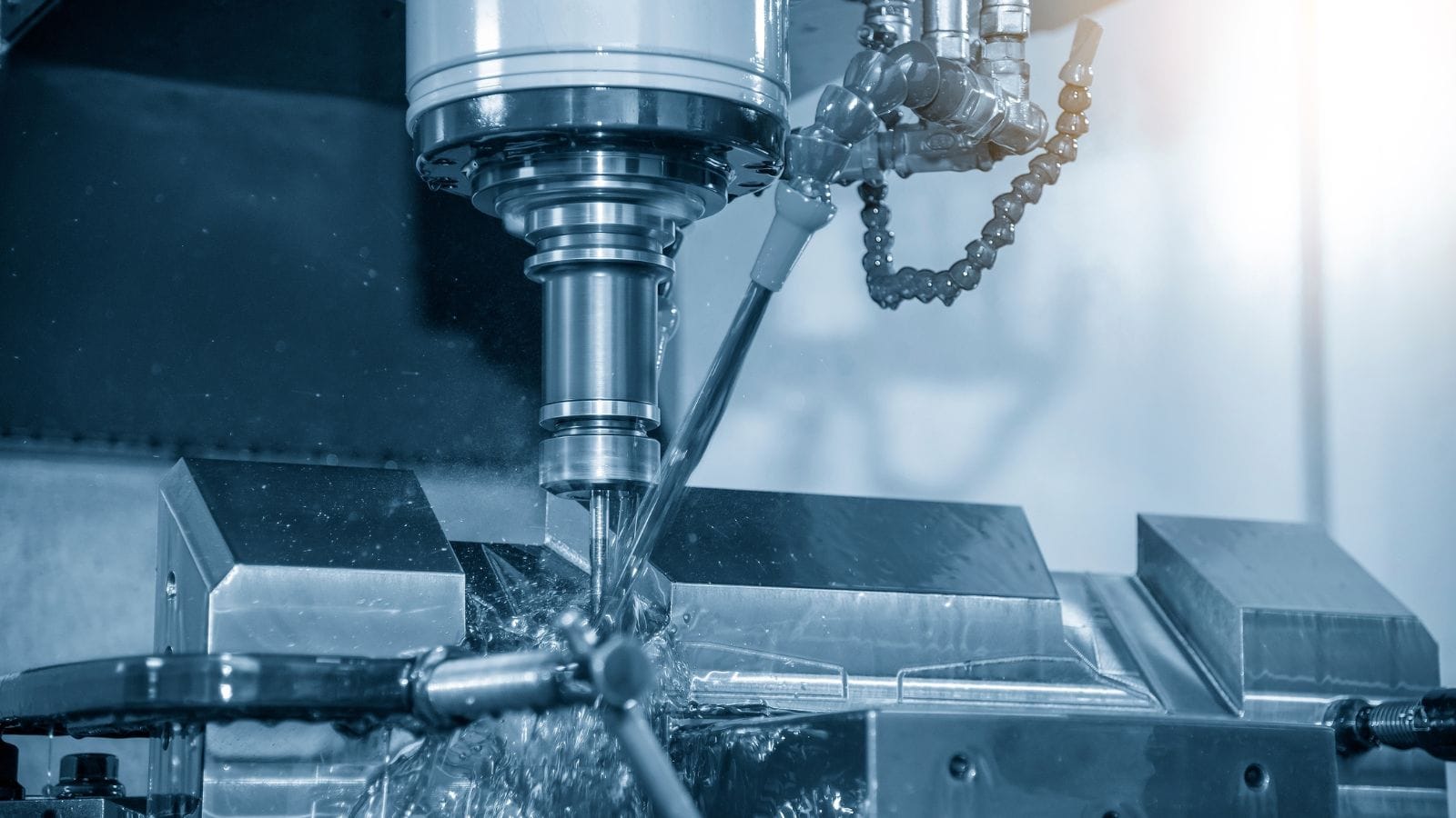
With design finalized and materials procured, fabrication begins in the tool room. Lathes perform initial rough machining on the tool steel blocks, removing bulk material efficiently. CNC machining centers then execute precision rough and finish passes on the blocks, cavities, and cores to achieve final specifications.
If the design involves intricate geometries that conventional cutting tools cannot achieve, EDM (electrical discharge machining) can be introduced for better results: wire EDM cuts intricate profiles, while sinker EDM creates complex cavity shapes by eroding material with a shaped electrode. These processes are essential for achieving the fine detail and tight radii common in die casting molds.
Final Verdict: Assembly, Tryout, And Process Validation
Once assembled, the mold undergoes a tryout, which is a controlled test run on the production press or casting machine. Sample parts are produced and measured against the design specifications.
Dimensional inspection using coordinate measuring machines (CMMs) verifies that critical features fall within tolerance. For die casting molds, X-ray inspection may be used to check for internal porosity.
If discrepancies are found, the mold is adjusted, re-tested, and approved only after parts consistently meet all quality requirements. This validation step is the final gate before full production begins.
Moldiecasting Capabilities: Die Casting Molds and Production Parts
Our capabilities span mold design, premium material sourcing, in-house tooling build, casting, secondary processing, and inspection. For die casting tooling manufacturing, Moldiecasting stands as a single accountable partner from the first drawing to finished parts.
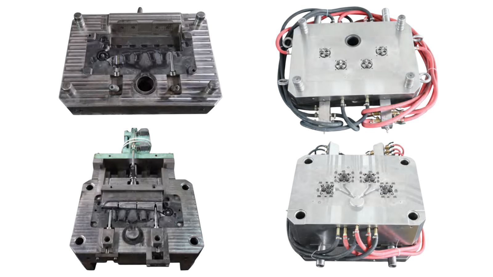
A Wide Range of Molds for Every Die Casting Application
Backed by in-house precision CNC and wire/sinker EDM capabilities, we design and build molds for the full range of die casting applications, including
- Single-cavity molds
- Multi-cavity molds
- Family molds
- Molds with complex side actions such as slides and lifters for undercut features
- And more
Our rich experience in the global mold-sourcing market also makes sure our tooling adheres to multiple regional quality standards such as HASCO and ASTM. This guarantees that our molds can be easily integrated into your aluminum, zinc, and magnesium alloy parts production lines, accommodating both cold chamber and hot chamber processes.
For projects that require physical validation before committing to production tooling, we can also support rapid tooling options to produce prototype sample parts earlier in the development cycle.
Premium Material Sourcing Across Leading Tool Steel Brands
Mold performance and service life begin with material selection. Moldiecasting sources tool steels from globally recognized suppliers, giving us access to the full range of grades required for different die casting conditions and service demands.
For die casting tooling, typical choices include hot-work grades such as 8407, DIEVAR, SKD61, and DAC55.
For molds requiring mirror-surface cavities, corrosion resistance, or specialized cold-work properties, we draw from the same supplier network to match material to application precisely.
A Rigorous, Fully Documented Production Process
As an experienced tool and die maker, Moldiecasting boasts an established production and inspection routine that provides you with cost-effective mold solutions, ensuring visibility, control, and documented proof of quality while offering faster lead time and higher productivity.
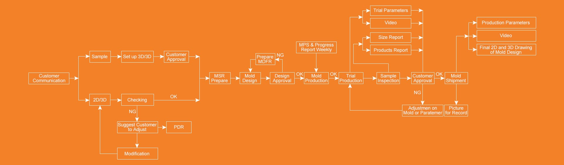
The process begins with customer communication and file review:
- For 2D/3D submissions, we first check geometry and flag issues. Where design changes are recommended, we work through a PDR (Part Design Review) cycle.
- For physical samples, we can set up 3D scanning for reverse engineering. Once inputs are confirmed, we complete MSR (Mold Structure Review) preparation before mold design begins.
Mold design goes through a formal approval gate before production starts. Throughout the mold production phase, we issue weekly MPS progress reports so you have a clear view of tooling status.
Once the tooling is ready, we would then run a controlled trial production and deliver a full package: trial parameters, a production video, a full-size inspection report, and a product report.
For the sample products, we use CMM measurement, X-ray inspection for internal integrity when required, and 3D scanning for dimensional verification. If inspection reveals issues, we carry out mold or parameter adjustments and re-inspect before seeking approval.
Only after your sign-off does the mold ship with production parameters, and final 2D/3D mold drawings, which will be helpful for your future production and maintenance reference.
Frequently Asked Questions
What files do you need to quote a die-casting mold?
To quote accurately, we typically need a 3D model (STEP or IGES), alloy requirement, target annual volume, cosmetic requirements, and any critical tolerances. If you have a 2D drawing, please include it to clarify datum strategy and inspection requirements.
Do you provide inspection reports and validation after tryouts?
Yes. Depending on project requirements, we can provide CMM measurement reports, 3D scan reports, and (when required) X-ray inspection for internal integrity. Validation is completed through trial runs and iterative adjustments until parts consistently meet the agreed specifications.
How do you help determine which tolerances are worth the cost?
Not all tolerances have equal impact on function. We work with you to identify which dimensions are truly critical and which can tolerate wider ranges. This distinction typically reduces tooling and machining costs while ensuring tight tolerances.