Die casting post machining, combined with the die casting process, produces finished, dimensionally accurate parts. But the real production challenge is not casting or machining in isolation; it is designing both steps to work together so that cycle times stay short, scrap stays low, and parts meet the expected parameters.
Why Are CNC Operations Needed After Die Casting
Common reasons to add CNC operations include:
- Achieving tolerances tighter than as-cast capability
- Creating precision bores, threads, and sealing surfaces
- Removing parting line marks
- Opening features that cannot be cast
CNC Operations and Tolerances for the Die Casting Process
Even the best die casting process has limits on the tolerances and surface finishes it can achieve in the as-cast state. CNC machining bridges that gap, bringing critical features to the precision levels required for fit, function, and appearance.
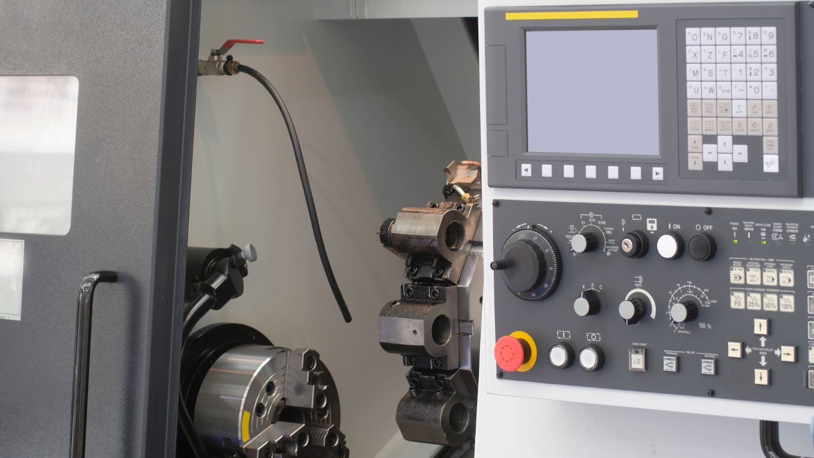
CNC Steps for Die-Cast Components
The most frequent machining operations performed on die-cast parts include:
- Milling: Flattening mating surfaces, creating pockets, and machining complex contours
- Drilling and tapping: Producing precision holes and threaded features
- Turning: Machining round features, often on parts fixtured in a lathe or rotary table
- Deburring: Removing sharp edges and residual flash from cast and machined features
- Grinding and polishing: Achieving fine surface finishes on functional or cosmetic areas
As-Cast Capability vs Machined Precision
Die casting delivers good dimensional accuracy by casting standards, and some of the parts produced by the method don’t require machining, but there are real limits, as seen in this chart:
| Parameter | As-Cast (Typical) | After CNC Machining |
|---|---|---|
| Linear tolerance | ±0.1 mm to ±0.3 mm | ±0.01 mm to ±0.05 mm |
| Surface roughness (Ra) | 1.6 to 6.3 µm | 0.4 to 1.6 µm |
| Flatness | 0.1 to 0.3 mm over 100 mm | 0.02 mm or better |
| True position (holes) | ±0.2 mm | ±0.05 mm or better |
As-cast tolerances are defined by standards such as NADCA and ISO 8062. Features that cross the parting line or involve movable cores typically carry wider tolerance bands.
Also, surface treatments such as anodizing require specific alloy chemistry, and machined surface roughness targets must be compatible with the finishing method.
Design Rules That Reduce Post Machining Time
Smart mold design is the most effective way to cut machining time and cost. Decisions about gating, venting, wall geometry, and datum placement made during tooling design directly control the quality, consistency, and machinability of the as-cast part.

Mold Layout, Gating, and Venting Fundamentals
A die casting die consists of two halves: the cover die (stationary) and the ejector die (movable), and where they meet is the parting line that determines flash location and influences which surfaces need post-machining. What’s more, gating systems and venting channels also greatly influence the quality of parts, which in turn affects machining.
The gating system includes the sprue, runners, and gates that direct molten metal into the cavity. Gate location and size affect fill pattern, air entrapment risk, and the location of gate vestige on the finished part. A poorly placed gate can cause turbulent fill, cold shuts, and porosity in areas that later need machining.
Venting allows trapped air and gases to escape during injection. Vents are thin channels cut into the parting line or placed at the last areas to fill. Insufficient venting leads to air entrapment and porosity, especially damaging when those regions require machined sealing surfaces.
Advanced mold design tools, including CAD/CAM/CAE software and mold flow analysis (fill time, temperature distribution, air pressure, shrinkage prediction), help engineers optimize gate locations and vent placement before cutting steel.
Part Geometry for Strength, Flow, and Release
Several design rules directly impact whether a casting can meet dimensional targets with minimal machining:
- Draft angles: All surfaces parallel to the die opening direction need taper for clean ejection. Aluminum typically needs at least 1:100 (0.6°); zinc can use as little as 1:200 (0.3°).
- Fillets: Replace sharp internal corners with radii to improve metal flow and reduce stress concentrations. This can also reduce premature mold wear.
- Ribs: Add structural stiffness without increasing wall thickness. Keeping rib thickness at roughly 60–80% of the adjoining wall can avoid sink marks.
- Uniform wall thickness: Huge variations in wall thickness can cause uneven cooling, warpage, and internal porosity. The thickest section should stay under 13 mm when possible.
- Bosses: Use consistent wall thickness around mounting bosses to reduce shrinkage porosity.
Planning Machined Features and Datum Strategy
Features that will be machined should be designed with adequate stock allowance, typically 0.5 mm to 1.0 mm, depending on part size and alloy. Too little stock means the machining cutter may hit as-cast porosity; too much adds cycle time and tool wear.
Datum strategy is equally important. Datum surfaces are the reference points used to fixture the casting in the CNC machine. These should be:
- As-cast surfaces with minimal flash or distortion
- Located to allow a stable three-point (3-2-1) fixture setup
- Consistent from shot to shot to avoid position scatter during machining
Engineers who plan datum and fixture schemes at the mold design stage, rather than after casting, save significant time in machining setup and reduce scrap from mislocated features.
Defects, Inspection, and Quality Assurance
Even a well-designed die casting process produces parts that must be verified before shipment. Casting and machining defects each introduce unique risks, and a thorough quality assurance system catches problems before they reach the assembly line.
Common Casting and Machining Defects
Die casting defects include:
- Porosity: Small voids caused by trapped gas or shrinkage during solidification
- Cold shuts: Visible lines where two flow fronts met but did not fully fuse
- Flash: Excess metal along the parting line or around core pins
- Misruns: Incomplete cavity fill due to insufficient metal temperature or pressure
- Surface blisters: Caused by subsurface gas pockets that expand during heat treatment or machining
Machining-related defects include:
- Tool marks or chatter from worn or improperly set cutters
- Out-of-tolerance features from fixture errors or datum shift
- Exposed porosity when machining removes the dense skin layer of the casting
How Porosity and Air Entrapment Affect Secondary Operations
Porosity is the single most common defect that connects casting quality to machining outcomes. The outer skin of a die casting, typically 0.5 mm thick, is dense and relatively pore-free because it solidifies quickly against the die wall. The interior can contain gas porosity or shrinkage voids.
When machining removes this dense skin, it may expose pores that compromise sealing ability, surface finish, and structural integrity. This is why machining stock allowance, gate placement, and venting all need to account for porosity risk in regions that will be machined.
Mold flow analysis, specifically air pressure and shrink hole simulations, helps predict where porosity will occur so designers can either move the feature, add venting, or adjust process parameters.
Inspection Methods for Production Approval
A reliable quality system uses multiple inspection methods at different stages:
- Dimensional inspection: Coordinate Measuring Machines (CMMs) verify critical dimensions against the part drawing. First-article inspection reports are standard for new tooling.
- X-ray inspection: Non-destructive examination reveals internal porosity and inclusions without cutting the part. Essential for structural and pressure-tight castings.
- 3D scanning: Compares the entire as-cast or machined surface to the CAD model. Useful for detecting warpage, shift, and profile deviations.
- Material testing: Spectrometer analysis confirms alloy chemistry. Hardness and tensile testing verify mechanical properties.
- Visual inspection: Projectors and optical comparators check surface quality, flash residue, and cosmetic defects.
Suppliers with certifications such as ISO 9001:2015 and IATF 16949 follow documented quality plans that define inspection frequency, measurement equipment, corrective action procedures, and traceability.
Applications and Cost Drivers of Die Casting Machining
Die casting machining serves a wide range of markets, and the total cost of a finished part depends on far more than the per-piece casting price. Smart sourcing decisions start with matching the application to the right alloy, process, and manufacturing partner.
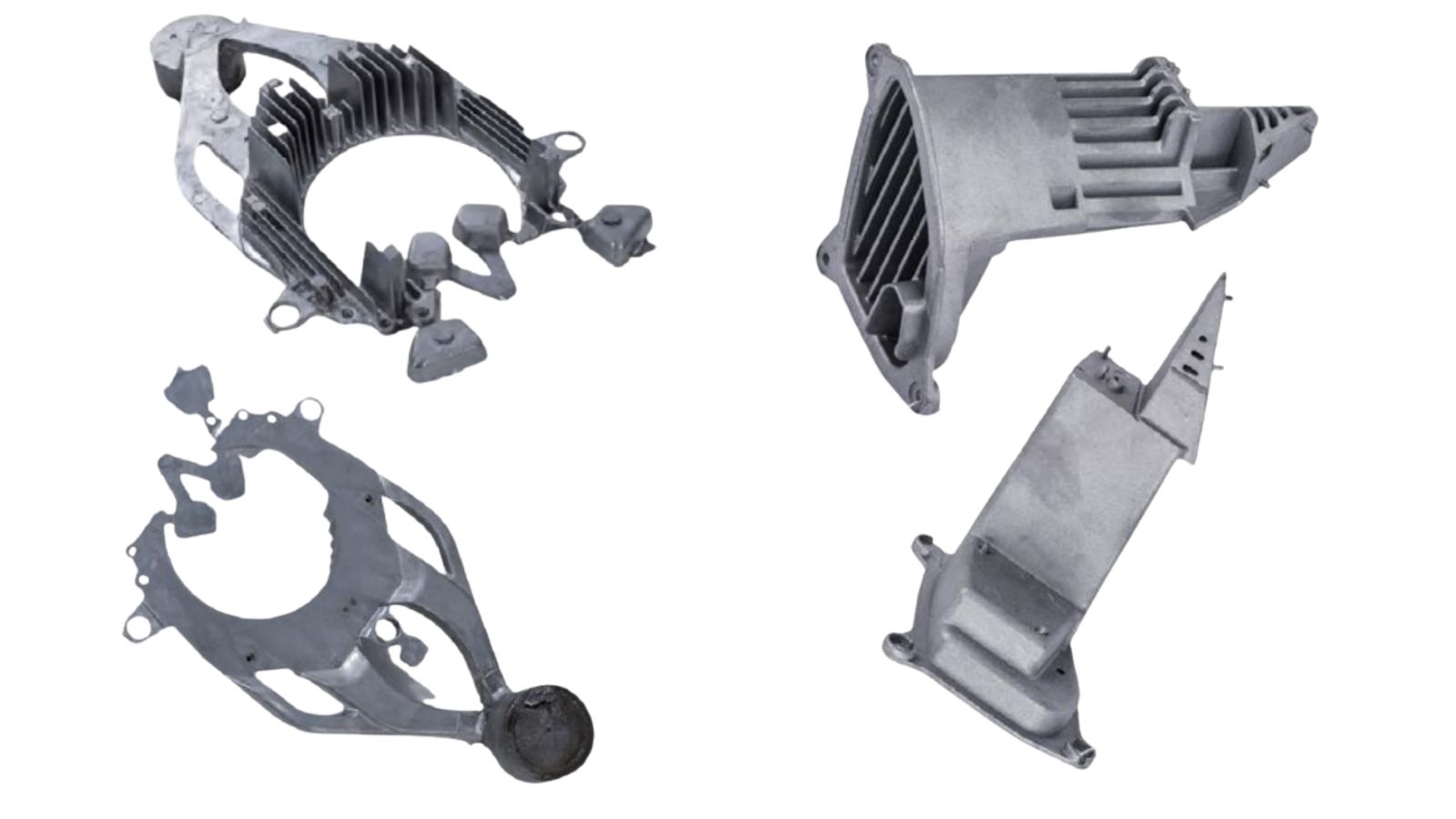
Best-Fit Industries and Typical Part Types
Automotive is the largest consumer of die-cast and machined parts. Engine blocks, transmission housings, structural brackets, and EV battery enclosures all rely on aluminum or magnesium die casting followed by precision CNC operations.
Aerospace demands lightweight, high-integrity parts. Magnesium and aluminum castings are machined to tight tolerances and inspected by X-ray for internal soundness.
Consumer electronics uses zinc and aluminum die castings for device housings, heat sinks, and connector bodies. Surface finish quality is critical for consumer-facing products.
Industrial and medical equipment benefits from the repeatability of die casting for motor housings, valve bodies, and enclosures that require dimensional consistency across large production runs.
What Drives Machining Cost
Cycle time is dominated by feature density and toolpath difficulty. Threads, precision bores, sealing faces, deep pockets, intersecting holes, and complex contours add tool changes, longer cutting paths, and slower feeds for stability. Cost rises especially fast when tight tolerances are paired with poor tool access or long-reach tools, because chatter control often requires additional semi-finish/finish passes.
Setup count is the most reliable predictor of cost escalation. Every extra re-clamp adds handling, probing, risk of datum shift, and often a dedicated fixture. Even if the cut time is similar, multiple setups reduce throughput and increase the probability of out-of-tolerance parts, so the effective machining cost becomes “cost per conforming part,” not “cost per cycle.”
Variability in the casting converts into hidden machining costs. When the as-cast condition varies, manufacturers compensate with more probing, larger stock assumptions, slower parameters, and sometimes manual touch-up. Those compensations increase both time and tool wear, and they raise the likelihood of rework loops that are expensive but rarely visible in per-piece quotes.
Yield loss is the silent cost driver. Any condition that causes parts to fail after machining, whether due to dimensional nonconformance, leak failures, or cosmetic rejects, amplifies cost because the machining time has already been spent.
Choosing a Full-Service Partner That Protects Cost, Quality, and Lead Time
The fastest way to reduce risk in die casting machining is to treat tooling, casting, CNC machining, finishing, and inspection as one integrated process, not a chain of handoffs. Consolidating these steps under a single full-service partner typically shortens lead times, simplifies accountability, and reduces the chance of damage or variation being introduced between vendors.
If you want to move from “Can they make it?” to “Can they make it reliably at scale?”, Moldiecasting can help: reach out to us for a wide alloy and process coverage with engineering support, as well as in-house machining team, recognized certifications (ISO9001 and IATF16949), and complete post-processing capability!