Die casting design shapes every aspect of a die cast part on a fundamental level. A strong design balances material choice, geometry, and tooling needs, which also reduces defects, limits extra machining, and extends tool life. This article explains the die casting rules in a logical order to show how careful designs for manufacturing lead to reliable parts and efficient production.

Key Principles and Objectives of Die Casting Design
Die casting design aims to produce consistent parts at the lowest practical cost. Engineers focus on casting quality, tool life, and short cycle time from the start.
Key objectives include:
- Minimize porosity and air entrapment
- Control flash and parting line location
- Support proper gate and runner layout
- Protect die life under high pressure
Design Goals of Die Casting Material Selection
Material selection is the very foundation of a die casting project. Engineers start alloy selection by gathering information, which mostly comes from customer’s design requirements. Then, engineers use this information to set desirable goals for designs.
Weight Reduction and Density Limits
In industries like automotive, aerospace, and portable electronics, minimizing a component’s mass is a primary design objective. The physical density of the chosen alloy strictly dictates the final weight of the part. Engineers must carefully evaluate the strength-to-weight ratio to ensure the part remains light enough for its specific application without sacrificing critical structural integrity.
Cost Optimization and Production Economics
Beyond physical performance, material selection is heavily constrained by strict budget limits outlined in the initial project scope. True cost optimization requires balancing the raw price of the metal against its overall impact on the manufacturing cycle for better manufacturability.
For example, alloys with lower melting points naturally extend the lifespan of expensive steel casting dies, but they may lack other properties needed for the products. The key to this process is compromise and evaluation, so engineers can arrive at a solution that is more qualified for the projects than other materials.
Thermal Physics and Manufacturing Variables
Before evaluating a part’s final strength, engineers must first factor in how the metal behaves during the actual die casting process. Manufacturing variables, specifically thermal physics and mold cooling and solidification rates, fundamentally alter a material’s inherent characteristics. Rapid cooling inside the die creates a dense, fine-grain structure that significantly enhances the material’s baseline strength.
Mechanical Properties and Operational Strength
Building upon the structural foundation established during the cooling phase, the specific alloy choice directly defines the component’s baseline mechanical capabilities. These critical metrics include tensile strength, yield strength, elongation (ductility), and overall hardness.
Together, these specific properties govern exactly how well the finished part will handle continuous mechanical loads, sudden physical shock, and friction-induced wear throughout its active lifespan.
Corrosion Resistance and Long-Term Viability
Once the mechanical capabilities are secured, engineers must account for environmental resistance to guarantee the product’s long-term survival during exposure to corrosive agents like salt, ambient moisture, or industrial chemicals.
If the chosen alloy’s mechanical properties are perfect but its environmental resistance is weak, engineers must plan for secondary surface finishes to protect the final product.
[Die casting makes use of a wide range of metals. For more information on specific die casting alloys, refer our extensive die casting material guide!]
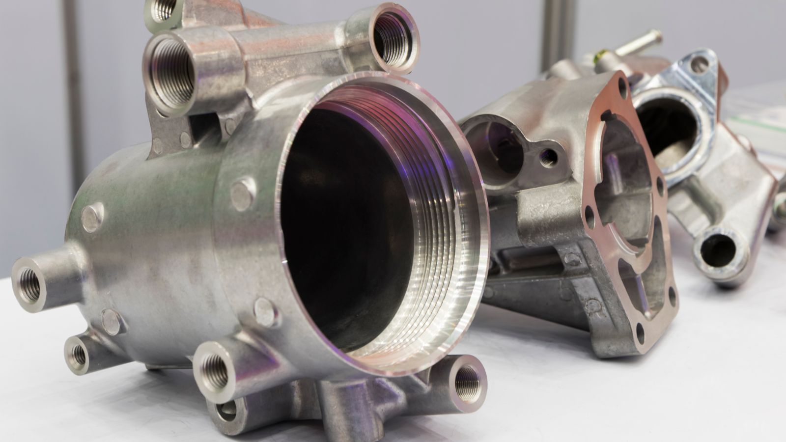
Critical Geometry and Feature Design
Geometry controls how metal fills the die, cools, and ejects. Designers must control wall thickness, apply proper draft angles, define clean parting lines, and use fillets and radii to prevent stress concentrations and tool wear.

Wall Thickness and Uniformity
Wall thickness drives fill, cooling time, and defect risk. Most aluminum die castings use 1.5–3.0 mm walls, zinc can go thinner to 0.75–2.5 mm, and magnesium often falls between 1.25–2.0 mm. Designers confirm the minimum wall thickness with the selected alloy and supplier data.
They aim for uniform wall thickness across the part. Sudden jumps greater than 1.5× between adjacent sections create hot spots. These areas cool slowly and often cause sink marks or internal porosity.
When strength is needed, they also avoid thick solid sections. Instead, it is possible to core out heavy areas and add ribs, which maintain stiffness while preserving consistent wall thickness and stable cooling.
Draft Angles and Parting Lines
A proper draft angle allows the part to release from the die without damage. As a rule, designers apply at least 1° draft on external walls and 2° on internal features. Deeper cavities require more draft, often adding 1° per 25 mm of depth.
Designers also define clear parting lines early in the design. A flat, simple parting line reduces flash and tool complexity. Poorly placed parting lines increase mismatch, trimming work, and cost.
Fillets, Radii, and Corners
Sharp internal corners restrict metal flow and create stress concentrations. Under load, these corners can raise local stress by two to three times. They also shorten die life because sharp edges in the cavity crack under heat and pressure.
Designers use fillets and radii at all wall intersections. A common rule sets the minimum internal radius at about 0.5 × wall thickness, with many applications using 0.75 mm or more. Larger radii improve flow and reduce porosity risk.
External corners also benefit from radii. Rounded external corners reduce chipping and improve coating coverage.
Structural Elements and Complex Features
Ribs, bosses, holes, and undercuts shape how die-cast components fill, cool, and eject from the die. Proper design of these features controls porosity, stiffness, tool life, and assembly accuracy.
Ribs and Boss Design
Ribs increase stiffness without adding thick walls. Designers use ribs to control warpage and reduce weight in large flat areas.
A common rule sets rib thickness at 0.6–1.0 × the nominal wall thickness (T). As for rib height, it often stays below 5 × T to avoid filling problems and weak tall sections.
Designers add a fillet radius near the wall thickness at the rib base. They also apply a 1–3° draft to support clean ejection.
Boss design follows similar limits. Tall or solid bosses create hot spots and internal voids.
Key boss guidelines:
- Keep boss wall thickness close to T
- Core out large bosses to keep walls uniform
- Add support ribs to improve strength and metal flow
- Maintain space between bosses and nearby walls to protect die steel
Holes, Windows, and Undercuts Design
Holes and windows affect filling, venting, and die strength. Small or deep features are harder to cast cleanly.
For many aluminum die-cast components, practical minimum hole diameters start near 2 mm. Designers limit depth to about 4–6 times the diameter when possible. Deeper holes may require secondary drilling.
Whenever possible, they use cored holes instead of machining solid material. Cores reduce weight and control shrinkage, but they must leave enough steel in the die for strength.
Windows and large cutouts should have:
- Rounded corners to reduce stress
- Uniform wall thickness around the opening
- Smooth transitions to nearby ribs or bosses
Undercuts increase tooling cost. They require side cores or slides, which add moving parts and raise maintenance needs. Designers often revise geometry to align features with the main draw direction and avoid unnecessary undercuts.
Special Features and Thread Design
Threads and added features require careful planning in die casting. Designers must balance cost, tool life, strength, and assembly needs when choosing between cast-in details and secondary machining or inserts.
Designing Threads: Cast-in vs. Post-Machined
Designers often choose between die cast threads formed in the tool and threads cut after casting.
Cast-in Thread: It reduces secondary operations. They work well for larger external threads where slight variation is acceptable.
However, full external thread forms can create parting line alignment problems, and internal threads cast directly into the part usually require special cores or side actions, which raise die cost and increase wear.
Machined Thread: Small or precise threads often perform better when machined after casting. Post-machined threads provide tighter tolerances and smoother finishes. They also avoid tool damage from thin or fragile cores.
In many cases, teams drill and tap internal holes instead of casting them. This method improves consistency and extends die life. Compared to injection molding, die casting handles metal threads with higher strength, but it still faces similar draft and ejection limits.
Functional Inserts and Assembly Methods
Functional inserts add strength and improve wear resistance in high-load areas. Designers can place steel or brass inserts into the die before metal injection. The molten alloy flows around the insert and locks it in place.
This method works well for threaded bosses that face repeated assembly. It reduces stripping and improves long-term durability. However, insert placement increases cycle time and requires precise fixturing.
For post-casting threaded inserts in metal, engineers use press-fit inserts, Heli-Coils (wire thread inserts), or Keenserts (key-locking inserts), which are mechanically threaded or pressed into a pre-drilled/cast hole, rather than melted into place.
When adding ribs or bosses for threaded features, designers keep wall thickness uniform and add fillets at the base. This step reduces stress and supports smooth metal flow. Proper draft on bosses also ensures clean ejection and protects the tool.
Post-Casting Operations: Machining and Surface Finishes
Deciding what happens after the part leaves the mold is a critical step in die casting design. Efficient coordination between the raw casting design and post-casting steps lowers scrap rates and shortens overall production lead times.
Machining Allowances and Datum Planning
While die casting produces near-net shapes, many parts still require CNC machining after casting to meet incredibly tight tolerances. Engineers must include a defined machining allowance on critical surfaces during the design phase. This extra material ensures cutting tools can remove surface variation, minor porosity, or dimensional shifts without cutting into the structural core of the part.
To optimize this process, engineers must plan datum locations during the initial die design. Clear datum control guarantees that the part sits identically in the CNC fixture every time, which improves repeatability during post-machining and supports accurate metal assembly.
Surface Finish Selection and Design Impact
Die casting can produce remarkably smooth surfaces, but most parts require some level of mechanical or chemical post-processing to meet final aesthetic or functional specifications. Because the chosen surface finish interacts directly with the cast metal, designers must account for coating thicknesses, edge build-up, and surface integrity during the CAD phase.
Common post-processing methods include:
- Anodizing: Forms a protective oxide layer on aluminum parts.
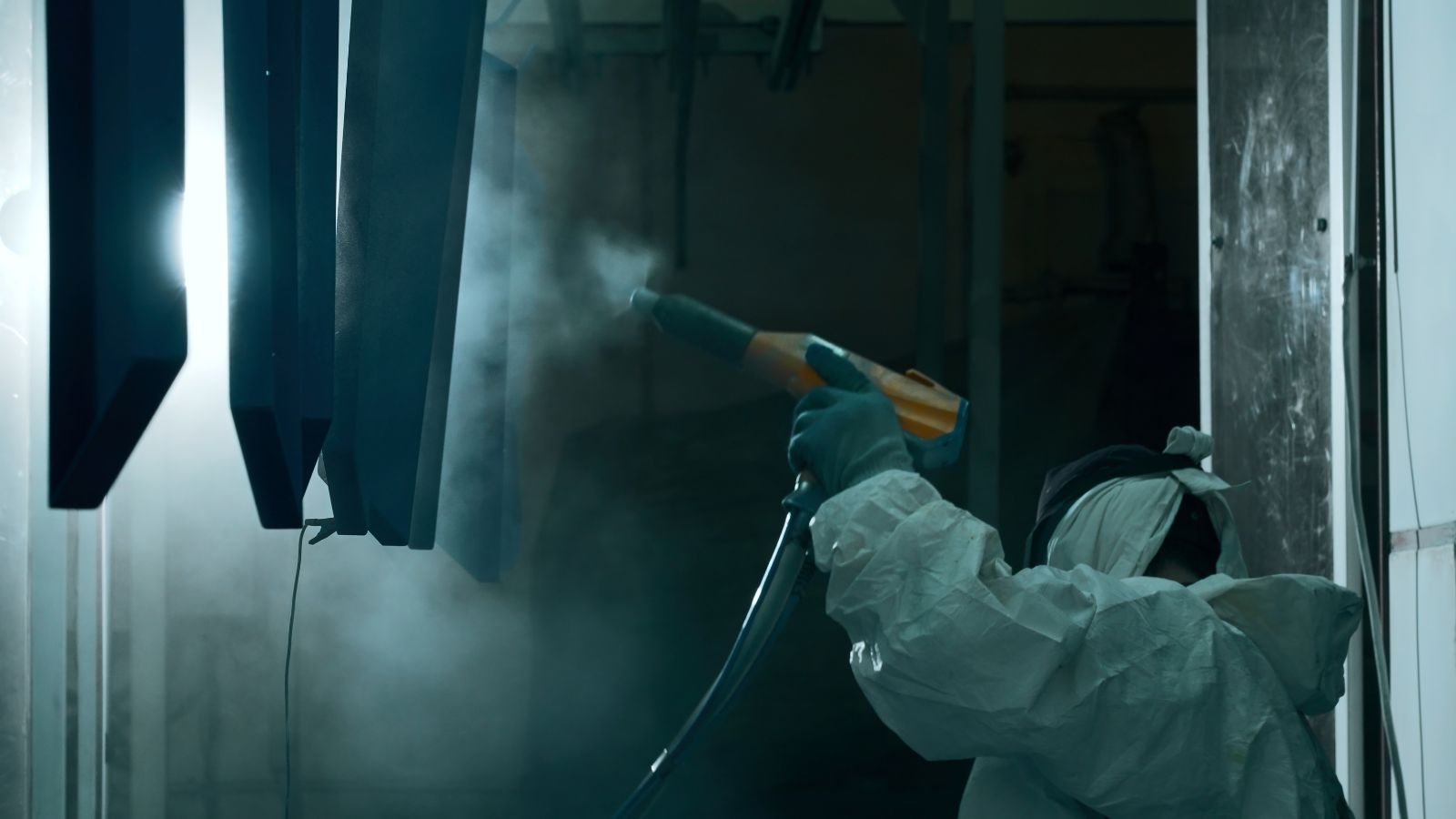
- Powder coating: Applies a dry powder that cures under heat into a highly durable layer.
- Painting: Adds basic protection and visual appeal at a lower cost; often used for parts not subjected to extreme wear.
- Plating: Deposits a thin metal layer (like zinc, nickel, or chrome) to drastically improve wear resistance, EMI shielding, or electrical performance.
- Deburring or blasting: Mechanical processes (like tumbling or sandblasting) that remove sharp edges, parting line flash, and surface defects prior to applying other liquid or powder coatings.
How Surface Finish Requirements Influence Die Casting Design
The finish you choose actively dictates how you must design the geometry of the part. The chart below illustrates how different post-processing methods require specific design adjustments before the mold is ever cut.
|
Surface Finish Method
|
Impact on Part Tolerances
|
Key Design Adjustments Required
|
|---|---|---|
|
Powder Coating
|
Adds significant thickness (0.05–0.15 mm per surface).
|
Reduce boss diameters and widen hole clearances for mating parts. Threads must be masked or tapped after coating.
|
|
Plating (Chrome/Nickel)
|
Minimal thickness change, but highly sensitive to part geometry.
|
Requires generous external radii, as plating aggressively builds up on sharp corners. The design must minimize porosity, as trapped gas causes the plating to blister.
|
|
Anodizing
|
Negligible thickness change, but it penetrates the metal surface.
|
Only limited to certain alloys like specialized low-silicon alloys. Draft angles must be smooth, and gate locations must be moved away from highly visible cosmetic surfaces.
|
|
Painting
|
Adds moderate thickness depending on primer and coat count.
|
Can mask minor flow marks and shallow surface flaws. Requires careful planning of parting lines so flash removal doesn’t ruin the painted surface.
|
|
Abrasive Blasting
|
Removes a microscopic layer of material; alters texture.
|
Requires slightly larger draft angles on textured walls to ensure clean ejection before the blasting process homogenizes the surface.
|