


Engineers and sourcing managers know the extra cost that a mold revision at the die casting stage could bring. To prevent that, prototype die casting is introduced into the die casting workflow.
Fundamentally, prototype die casting is the practice of producing small batches of functional metal parts to test design viability and manufacturability before investing in hardened, mass-production molds, but the challenge is that it is not a single method. This method spans single-cavity steel dies, machined billets, and investment castings.
Therefore, this guide is here to help you decide the major prototype routes, covering alloy selection, design rules, and how to transfer learnings into high-volume production.
When is Prototype Casting the Right Choice?
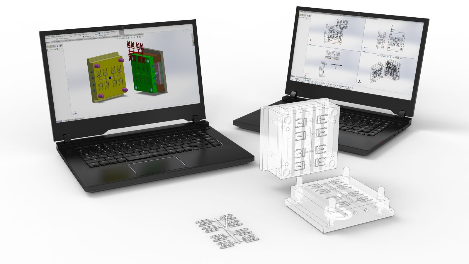
Not every project requires a cast prototype, but some validation goals simply cannot be met by machined or 3D-printed parts. Cast parts carry residual stress patterns, skin density, and porosity characteristics that come from the casting process itself, not from material stock.
When a part requires vibration testing, thermal cycling, or load-bearing assembly, a cast prototype provides far more relevant data. Common pre-production validation checkpoints include:
- Dimensional conformance to tight 2D and 3D drawing tolerances.
- Structural integrity under application-specific mechanical loads.
- Surface finish acceptability for post-processing (anodizing, plating).
- Assembly fit with brackets, housings, or fasteners.
- Wall thickness verification across complex, thin-walled sections (under 2.5 mm).
Using mold flow analysis during this phase allows engineers to model fill velocity and temperature distribution. When simulation data aligns with physical prototype parts, the team gains confidence that the production mold design is sound.
Main Prototype Methods: A Comparison
The right choice depends on how closely the prototype must match the final production part and what the team needs to learn.
Single Cavity Prototype Dies
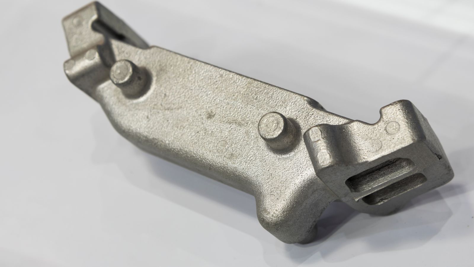
A single-cavity prototype die uses a real steel mold machined to produce one part per shot. As a primary cost control strategy, prototype dies are typically built from softer tool steel (like P20) or unhardened H13, rather than the expensive, fully hardened steel required for production.
This reduces the upfront tooling cost by 30% to 50% and significantly shortens machining time, while still producing shots under conditions that closely approximate high-pressure die casting, making it perfect for validating fill behavior, gate design, and cooling channels.
Machining From Solid (CNC)
Machining from billet stock is the fastest way to get a metal sample. However, machined parts lack the cast skin layer and grain structure formed during high-pressure injection.
Machined aluminum parts typically run about 15% weaker in yield strength compared to die-cast equivalents. It is excellent for early assembly checks, but a poor substitute for validating porosity or thin-wall behavior.
Investment Casting
Using 3D-printed wax patterns in place of hard tooling, investment casting produces metal prototypes that closely match the geometry of a production casting. It holds tighter dimensional accuracy than a machined billet on complex external features and is well-suited for aluminum parts undergoing structural testing.
Material Choices for Real-World Testing
Testing a prototype in the wrong alloy produces misleading data. The test results only predict production performance when the prototype alloy perfectly matches the intended production material.
- Aluminum (A380, A360): The standard for lightweight functional validation in automotive and industrial applications. Aluminum gives accurate data on wall thickness capability, surface finish quality (powder coating, anodizing), and dimensional behavior under temperature.
- Zinc: Used where fine detail, tight tolerances, and smooth-as-cast surfaces are required. Zinc flows at lower temperatures, meaning thinner walls and sharper features are achievable. It is ideal for electronics connectors and precision housings.
- Magnesium (AZ91D, AM60B): Selected where extreme weight reduction is a primary requirement. Magnesium produces thin-walled, near-net-shape parts that provide early data on structural behavior and mass targets simultaneously.
Design Rules & Cost Control Strategies
Prototype results—and tooling expenses—depend heavily on how the part is designed before the first shot is made. Controlling costs at the prototype stage means focusing your tooling spend only on the features that must be structurally tested.
- Prevent Over-Tolerancing: Every extremely tight tolerance requires secondary CNC machining or slower EDM (Electrical Discharge Machining) on the mold, driving up prototype costs. Only apply tight tolerances (± 0.1 to 0.2 mm) to critical functional areas; let non-mating surfaces remain as-cast.
- Simplify Geometry for Tooling: Undercuts, complex side-actions, and decorative textures add thousands of dollars to prototype mold costs. Simplify non-critical geometry (e.g., combining multi-piece assemblies or removing aesthetic ribs) to reduce tool complexity and keep budget focused on validating structural performance.
- Gating and Cooling: Prototyping with a real die lets the team validate gate position before the production tool is committed, helping avoid cold shuts and porosity.
- Secondary Operations: Design appropriate machining datums and fastener bosses early so prototype samples can undergo the exact same CNC machining or coating processes planned for mass production.
From Sample Approval to Volume Production
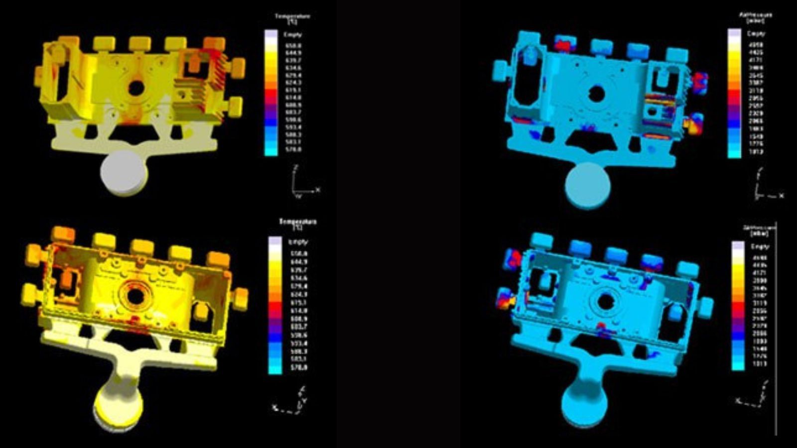
The most valuable outcome of a prototype program is the documented knowledge that transfers to the production tool. Gate locations that worked, cooling configurations that controlled warp, and alloy parameters that produced consistent fill become the baseline specification for the production die.
Prototype trials should produce documented inspection results, not just visual pass/fail assessments. Rely on suppliers equipped with CMM (Coordinate Measuring Machines) for dimensional verification and X-ray inspection for internal porosity checks is your best choice.
When a single supplier manages both prototype and production tooling, knowledge transfer happens seamlessly. The team that built the prototype tool uses that exact experience in the production mold design, reducing the risk of repeating problems at scale.
How to Request a Prototype Quote
Suppliers need complete technical data to provide meaningful quotes and avoid schedule delays. To get an accurate and fast prototype quote, it is advised for you to provide the following information:
- 3D CAD files (STEP, IGES, DXF, or DWG format).
- 2D drawings with critical tolerances clearly marked.
- Target alloy (e.g., Aluminum A380, Zinc Zamak 3).
- Volume estimates (Prototype quantity needed + estimated annual production).
- Secondary requirements (CNC machining, powder coating, assembly).
Note: If you only have physical samples, Moldie’s inspection department can 3D scan them to create the initial design.