

Mold flow analysis is a simulation technique used in die casting to predict how molten metal will move through a die. By running these tests on a computer, manufacturers can adjust key elements such as gate location, wall thickness, and alloy choice, reducing costly mistakes and saving valuable time.
For anyone involved in designing or producing die-cast parts, understanding mold flow analysis leads to better decisions, fewer surprises, and faster paths to production.
Core Principles of Mold Flow Analysis
Mold Flow Analysis allows engineers to see how molten metal will behave inside a die during the casting process. By understanding flow patterns, filling behavior, and key variables like pressure and temperature, manufacturers can improve product quality and avoid costly tool changes.
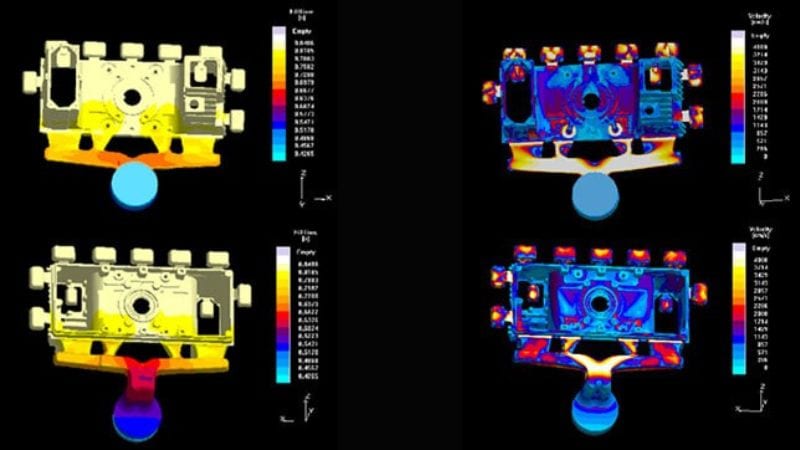
Simulation of Molten Metal Flow
Mold Flow Analysis uses computer-aided engineering (CAE) tools to create a virtual simulation of the die casting process. The software takes a 3D part model and predicts how molten metal will fill every part of the die cavity.
During simulation, the path and speed of the metal flow are shown in detail. This helps detect regions where the alloy might cool too quickly, get stuck, or fail to fully fill.
Engineers can also test different injection points or gating systems before committing to a die design. By visualizing the movement of metal, they adjust part features early to prevent problems like air traps, porosity, or incomplete sections.
Predicting Filling Behavior
Filling behavior is one of the most critical outputs of Mold Flow Analysis. The software predicts whether the molten metal will reach all areas of the die smoothly and evenly.
Potential issues like cold shuts, misruns, or air traps are highlighted on the part model. Cold shuts appear where different flow fronts meet at too low a temperature, which can cause weak spots in the casting.
With this information, engineers can change wall thickness, modify the layout, or select better gate locations to improve filling. They rely on these predictions to avoid defects, reduce waste, and ensure the finished casting closely matches its intended design.
Pressure and Temperature Distribution
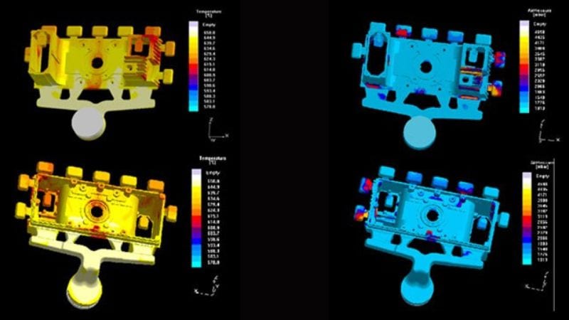
Mold Flow Analysis also simulates pressure and temperature across the die during filling and cooling. It tracks how much injection pressure is needed at different points and how heat moves through the die walls and the metal itself.
This data is used to find areas of high pressure, which can cause flash or even damage to the die components. Temperature maps show where the metal may cool too quickly or too slowly, leading to shrinkage porosity or thermal fatigue.
By understanding these pressures and temperature gradients, manufacturers can optimize the cooling system, improve cycle time, and lower the risk of defects. The end result is a more predictable, efficient, and cost-effective die casting process.
Optimizing Die and Part Design
Mold flow analysis helps engineers detect and prevent common casting defects before expensive tooling begins. This process improves overall part quality by focusing on crucial elements like die layout, part shape, material use, and how metal enters and moves inside the die.
Die Design and Cavity Configuration
Efficient die design begins with careful cavity configuration. The number and arrangement of cavities influence production output, but also impact filling balance and cooling rates.
A well-designed cavity reduces variations between parts. Mold flow analysis predicts how molten alloys, such as aluminum or zinc, move through each cavity. This lets designers correct early for issues like uneven packing or temperature differences.
Key design features include parting line positions, ejection locations, and cooling channel layout. Simulations show where redesigns are needed to minimize warping or shrinkage. Optimizing the die layout leads to better part consistency and faster cycle times.
Part Geometry and Wall Thickness
Part geometry, especially wall thickness, plays a major role in die filling and cooling. Thick sections cool slower than thin ones, which can cause shrinkage porosity or surface defects.
Mold flow analysis pinpoints areas where wall thickness should be adjusted for better filling or reduced stress. Using a uniform wall thickness wherever possible prevents defects and improves the structural integrity of the casting.
Sharp corners, deep ribs, or sudden transitions in wall size are highlighted by simulation for redesign. Modifying these features supports better metal flow and reduces production rejects. Simple shapes with consistent thickness keep the casting process stable and efficient.
Gate Placement and Venting Solutions
Gate placement controls how molten metal enters the cavity. Poor gate location or size can cause misruns, air traps, or excessive turbulence.
Simulation tools recommend gate positions that allow smooth, balanced flow without trapping air. Different gating systems are tested virtually before physical dies are machined. Correct gate sizing also avoids metal spraying or turbulence that impacts part integrity.
Venting is critical for air escape. Mold flow analysis finds areas likely to trap air, then suggests vent or overflow placement to release it. Proper venting saves time by reducing the need for tool rework and helps minimize porosity in the final parts.
Material Selection and Properties
The choice of alloy has a big influence on the die casting process. Different materials like aluminum, zinc, or magnesium have unique flow and cooling behaviors.
Mold flow analysis compares how these metals fill dies, revealing trouble spots before production starts. Properties like melting temperature, viscosity, and shrinkage rates are examined to ensure the material matches both design and functional needs.
Simulations help manufacturers test several alloys virtually, reducing mistakes and wasted material. By choosing the right metal and understanding its flow characteristics, engineers lower defect rates and improve the lifespan of both the part and the die.
Implementing Mold Flow Analysis in Manufacturing
Using Mold Flow Analysis (MFA) improves part quality, reduces defects, and lowers manufacturing costs. With the right approach and tools, MFA helps teams make better decisions about product design and the tooling process.
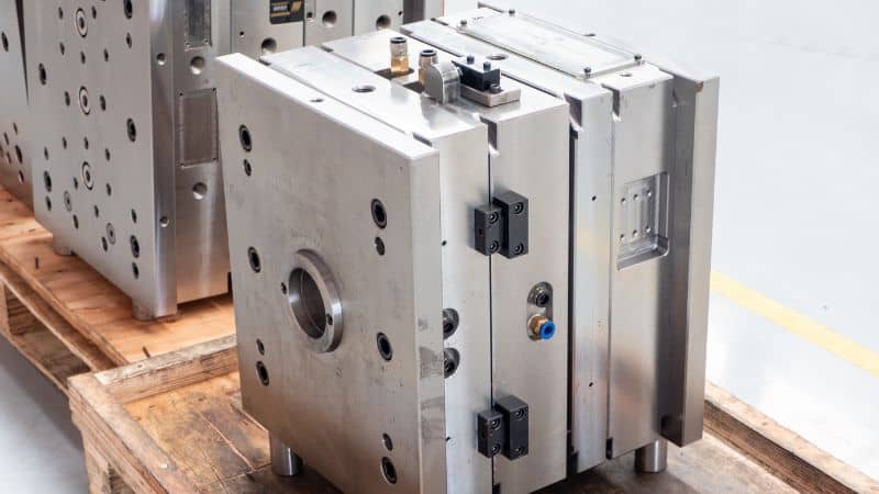
Integrating MFA in DFM and Tooling Processes
Incorporating MFA while working on Design for Manufacturability (DFM) allows engineers to predict fill patterns, detect possible trouble spots, and minimize porosity. Early simulation supports good decisions about gate locations, overflows, and wall thickness before cutting steel.
Collaboration between design teams and tooling engineers is essential. Sharing simulation findings leads to practical changes in die design—such as adjusting draft angles, vent placement, or cooling channel layout. This upfront effort helps lower the risk of problems like warpage or incomplete fills during later die trials.
Simulation Software and Analysis Workflow
Software like MAGMASOFT or FLOW-3D Cast allow detailed die casting simulations. Users import part geometry, select material data including thermal conductivity and viscosity, and set up process conditions such as temperature and pressure.
A typical workflow starts by simulating metal flow. Engineers analyze areas prone to pressure drop, misruns, or cold shuts. Then, the cooling phase is simulated to estimate solidification time, temperature gradients, and possible hot spots.
Reducing Lead Time and Cycle Time
MFA allows manufacturing teams to simulate multiple design alternatives without physical trials. By identifying and fixing issues early, they reduce the number of required die iterations.
Fast analysis of cooling layouts helps shorten cooling time, which is often the largest part of the cycle time. Understanding thermal conductivity and optimizing coolant paths leads to more uniform cooling and extends the life of the die.
By resolving issues in the virtual stage, teams can cut lead time for new tools. Production can also start sooner with fewer interruptions for tool adjustments or unexpected defects.
Frequently Asked Questions
How does mold flow analysis software integrate with CAD programs like SolidWorks or ANSYS?
Many mold flow analysis programs allow direct import of CAD files from SolidWorks and ANSYS. Some use plug-ins or built-in add-ins so engineers can run simulations directly within their CAD environment.
This integration means design changes in the CAD model quickly update in the analysis software. As a result, it helps save time and reduces errors during the design and simulation process.
What features distinguish the best mold flow analysis software in the industry?
Leading software usually includes advanced simulation tools like flow front tracking, solidification analysis, and porosity prediction. They support a wide range of metal alloys and provide detailed result visualization, such as pressure maps and temperature graphs.
Other helpful features include automatic mesh generation, support for multi-cavity dies, and easy report creation. Some programs also connect with company databases for material and project management.
Are there viable free alternatives to commercial mold flow analysis software for small-scale projects?
Some free or open-source programs offer basic casting simulations. These tools can be useful for students or small projects that do not need detailed results. However, free software often lacks advanced analysis features, user support, and frequent updates.
Users working on complex parts or requiring high accuracy may find commercial software more suitable. For simple tasks or learning purposes, free options may be enough.