Die casting is a metal forming process that creates precise, detailed parts by injecting molten metal into reusable molds.
It offers excellent dimensional accuracy, smooth surfaces, and complex shapes that would be difficult to achieve with other techniques.
Die casting starts with preparing a steel mold called a die. The die has two halves that come together to form a cavity shaped like the final part.
When the process begins, the die is clamped shut with tremendous force.
Molten metal is then injected into the die at high pressure. The metal fills all the spaces in the cavity very quickly which helps create detailed parts with thin walls.
After the metal solidifies, the die opens and the part is ejected. The process can repeat rapidly, making hundreds of identical parts per hour.
What is Die Casting Porosity
The high-speed nature of die casting makes some porosity almost inevitable.
Porosity refers to holes, voids, or pockets of air that form within or on the surface of a die-cast part. These defects range from tiny microscopic pores (micropores) to larger visible voids.
Sometimes it will be found as small indentations on the surface or be discovered internally during testing.
Think of porosity as unwanted spaces in what should be solid metal. These voids can appear in different patterns:
- Surface porosity: Visible on the outside of parts
- Internal porosity: Hidden within the part structure
- Gas porosity: Formed by trapped gases
- Shrinkage porosity: Created as metal cools and contracts
Porosity is actually common in die casting. Most manufacturers accept some level of internal porosity, but excessive or surface porosity can make parts unusable.
Causes of Porosity in Die Casting
Several factors contribute to porosity in die casting. The main culprit is trapped air or gas during the metal injection process. When molten metal rushes into the die at high speed, it can trap air that has nowhere to escape.
Poor temperature control also causes porosity. If the casting temperature is uneven, metal solidifies at different rates, creating voids.
Other common causes include:
- Inadequate venting in the die design
- Too much lubricant on die surfaces
- Improper gating or runner systems
- Incorrect metal injection speed
- Turbulent metal flow during filling
How to Prevent to Creat Much Porosity
Design Considerations
Start with a die design that promotes smooth metal flow. Avoid sharp corners and sudden thickness changes that can trap air or cause turbulence.
Include properly sized overflow wells and vents in your mold design. These features give gases somewhere to escape during the casting process, reducing trapped air bubbles.
Consider adding vacuum assistance to your die casting system. This helps remove air from the mold cavity before the molten metal enters, significantly reducing gas porosity.
Make sure your gating system directs metal flow in ways that push gases toward vents rather than trapping them.
Material Selection
Choose aluminum alloys with lower gas absorption properties when possible. Some alloys naturally resist hydrogen absorption, reducing the chance of gas porosity.
Ensure your metal is properly degassed before casting.
Remember to store materials in controlled environments to prevent moisture absorption. Humidity can introduce hydrogen into your alloys during melting.
You can also use flux treatments that help remove impurities that might cause porosity. Clean metal produces cleaner castings with fewer defects.
Process Parameters Control
Set the right temperature for both your metal and die. Too hot, and gases expand; too cool, and metal solidifies before gases escape.
Maintain consistent holding pressure during solidification. This helps prevent shrinkage porosity by forcing additional metal into areas that might otherwise form voids.
Watch out the cycle times and cooling rates. The cooling ensures gases have time to escape before the metal solidifies completely.
Porosity Detection and Measurement
Several methods exist to detect these hidden voids, ranging from simple visual inspections to advanced imaging technologies.
Non-Destructive Testing Methods
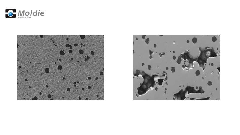
X-ray inspection is one of the most common ways to find porosity without damaging parts. This method creates images that show internal voids as darker spots against the metal background.
You can quickly scan multiple parts and identify problems without cutting anything open.
CT scanning (computed tomography) offers a more detailed 3D view of internal structures. This advanced technique lets you see exactly where porosity occurs within the part and measure its volume precisely.
CT scanning is especially useful for complex parts where porosity location matters.
Ultrasonic testing uses sound waves to detect discontinuities inside metal parts. When the sound waves hit a void, they reflect back differently.
This method works well for finding larger porosity clusters.
Quantitative Porosity Assessment
Measuring the amount of porosity helps you determine if a part meets quality standards. The Archimedes method compares the weight of a part in air versus liquid to calculate density differences caused by internal voids.
This simple approach gives you an overall porosity percentage.
Metallography involves cutting a sample, polishing the surface, and examining it under a microscope. You can measure the size and distribution of pores on the cut surface.
This method provides detailed information about specific areas but requires destroying the sample.
Image analysis software can quantify porosity from X-ray or CT scan data. The software calculates void percentages, sizes, and distribution automatically.
Addressing Porosity Issues
Remediation of Porous Castings
Inspect your castings under 5-10x magnification to properly identify porosity issues. This helps you determine whether the problem is gas porosity (rounded bubbles) or shrinkage porosity (irregular cavities).
For minor porosity problems, impregnation is effective. This process fills voids with a sealant, making parts pressure-tight. It’s commonly used for parts that must hold fluids or gases.
Secondary operations like hot isostatic pressing (HIP) can address internal porosity. This process uses high pressure and temperature to compress and eliminate internal voids.
Choose Moldiecasting For Your Next Project
Struggling with porosity in your die cast components? Gas porosity, shrink porosity, and voids caused by trapped air or uneven solidification can compromise the structural integrity of your cast parts, affect the mechanical performance, and lead to corrosion risks. At Moldiecasting, we specialize in advanced die casting process solutions to control porosity and deliver flawless results.
Our expertise in optimizing molten metal flow, high-pressure injection, and precision machine parameters ensures minimal shrinkage porosity and eliminates air trapped during the casting process. By tailoring wall thickness, alloy selection (including zinc and magnesium), and solidification controls, we address the causes of porosity at every stage. For critical applications, we offer vacuum impregnation or positive air pressure techniques to seal pores and enhance durability, even post-machining processes.
Why settle for defects? Partner with us for cost-effective, high-quality metal casting that prioritizes quality control and maximizes part performance. Contact us today at moldiecasting to discuss how we can impregnate confidence into your next project—ensuring every cast part meets the highest standards of precision and reliability. Let’s turn your porosity challenges into perfected solutions!
Frequently Asked Questions
What are the common types of porosity found in cast metals?
Die castings typically experience three main types of porosity issues. Gas porosity occurs when gases become trapped in the metal during solidification, creating small, rounded voids.
Shrinkage porosity forms when metal cools unevenly, creating irregular-shaped voids in thicker sections as the metal contracts.
Interdendritic porosity appears between the dendrite structures as the metal crystallizes, often in areas with slower cooling rates.
What are the ASTM E505 standard porosity levels for casting?
The ASTM E505 standard uses reference radiographs to classify porosity levels on a scale from 1 to 7. Level 1 indicates minimal porosity while level 7 shows severe porosity.