Die casting tolerances are a set of variations that ensure each component fits properly, functions as intended, and meets the required quality standards. Without proper tolerance control, even small dimensional differences can lead to assembly issues, reduced performance, or costly rework. This article aims to explore the standards, factors of die casting tolerances, as well as the best practices for manufacturers to maintain top-notch quality of their products.
Fundamentals of Die Casting Tolerances
Die casting tolerances set the allowed limits for variation in part dimensions to ensure proper fit, function, and performance. They depend on factors such as material properties, die design, and process control, and they define how closely the final product matches its intended measurements.
Definition of Casting Tolerance
A casting tolerance is the permissible variation between the actual measurement of a cast part and its nominal or design dimension.
In die casting, tolerances are expressed as a range, such as ±0.005 inches (±0.127 mm). This range accounts for natural changes during cooling, solidification, and handling.
These limits apply to all critical features, including thickness, hole spacing, and surface profiles. The value chosen depends on the part’s function, the manufacturing process capability, and the material’s dimensional stability.
Importance of Dimensional Accuracy
Dimensional accuracy ensures that parts fit together correctly without extra machining or rework. In assemblies, even small deviations can cause poor alignment, leaks, or mechanical failure.
Industries such as automotive, aerospace, and medical devices often require precision tolerances to maintain safety and performance. For example, an engine housing with loose tolerances could lead to vibration or sealing issues.
Maintaining accuracy also reduces scrap rates and improves production efficiency. By meeting the specified tolerance from the start, manufacturers avoid costly adjustments in later stages.
In practice, accuracy depends on consistent process parameters—such as melt temperature, injection pressure, and cooling time—combined with high-quality die design and maintenance.
Linear and Geometric Tolerances
Linear tolerances control allowable variation in straight-line dimensions like length, width, and thickness. For example, a ±0.005 inch (±0.127 mm) tolerance may be applied to a machined edge or hole spacing.
Geometric tolerances define the permissible variation in shape, position, and orientation. Common types include:
| Type | Purpose | Example Control |
|---|---|---|
| Flatness | Ensures a surface is even | ±0.002 in deviation across surface |
| Parallelism | Keeps surfaces aligned | ±0.003 in between planes |
| Angularity | Maintains correct angles | ±0.5° from design |
Both types work together to ensure parts are functional and interchangeable. Linear tolerances address size, while geometric tolerances ensure the part’s features align and interact as intended.
Die Casting Tolerance Standards
Die casting tolerances are set using recognized industry standards that define the allowable dimensional variation for cast parts. These standards differ by region and application, but most manufacturers follow guidelines from NADCA or ISO 8062 to ensure consistent quality and fit.
NADCA Tolerance Guidelines
The North American Die Casting Association (NADCA) publishes dimensional tolerance standards for aluminum, zinc, and magnesium die castings. These guidelines are widely used in North America for high-pressure die casting.
NADCA tolerances are based on part dimensions, metal type, and production method. They provide separate tables for Standard and Precision grades.
ISO 8062 and DCTG Grades
ISO 8062 is the international standard for casting tolerances. The current relevant part for die casting is ISO 8062-3, which defines DCTG (Dimensional Casting Tolerance Grade) levels.
DCTG grades range from DCTG 1 (tightest) to DCTG 16 (loosest). High-pressure die castings often achieve DCTG 4–6 without extra machining.
This specification allows global manufacturers to use a common tolerance reference, making it easier to compare specifications across suppliers.
Standard Tolerances vs Precision Tolerances
Standard tolerances represent the most economical level achievable in normal die casting production. They balance dimensional control with cost efficiency.
Precision tolerances are tighter and require more accurate die construction, better process control, and sometimes secondary machining. This increases production cost but can reduce downstream fitting or assembly issues.
Choosing between the two depends on part function, required fit, and budget constraints.
Factors Influencing Die Casting Tolerances
Dimensional accuracy in die casting depends on the interaction of material properties, part design, mold precision, and process stability. Each of these factors can cause variations that affect how well parts meet specified tolerances.
Material Selection and Alloy Type
Different alloys expand, contract, and solidify at different rates. For example, aluminum alloys typically have predictable shrinkage patterns, but variations in composition can still alter final dimensions.
Thermal conductivity and solidification shrinkage are key properties that influence tolerance control. Materials with high thermal conductivity cool more evenly, reducing warping and distortion.
Some alloys are more prone to internal stresses during cooling. This can lead to slight dimensional shifts even when the mold is accurate. Selecting a stable alloy with consistent quality reduces these risks.
Part Geometry and Draft Angle
Complex part geometry increases the chance of tolerance variation. Thin walls, deep cavities, and sharp corners can cause uneven cooling and shrinkage.
A draft angle—the taper applied to vertical surfaces—helps release parts from the mold without scraping or distortion. In aluminum die casting, a draft of 1°–3° is often recommended.
Insufficient draft can cause the part to stick in the mold, leading to deformation during ejection. Too much draft can affect fit in assembly. Balancing draft requirements with functional needs is essential.
Designers often simplify geometry in non-critical areas to improve tolerance control. Reducing deep recesses and extreme wall thickness differences can help maintain dimensional consistency.
Die Design and Tooling Quality
The precision of the die directly affects part tolerances. Any mismatch, wear, or defect in the mold cavity will transfer to the casting.
Cooling channel placement, venting, and cavity symmetry influence how metal fills and solidifies. Poor cooling design can cause localized shrinkage or warping.
Tool steel quality and machining accuracy determine how well the die holds its shape over repeated cycles. A high-quality die resists wear and maintains consistent cavity dimensions.
Regular maintenance, including polishing and dimensional checks, prevents gradual tolerance drift. In high-volume production, tooling wear is a common cause of dimensional variation.
Process Control and Machine Capabilities
Even with a precise mold, poor process control can cause parts to fall out of tolerance. Key parameters include injection speed, holding pressure, mold temperature, and molten metal temperature.
Modern die casting machines use sensors and controllers to keep these variables stable. Fluctuations in temperature or pressure can lead to dimensional shifts and surface defects.
Machine clamping force also plays a role. If the clamping force is too low, the mold may open slightly during injection, causing flash and dimensional errors.
Consistent monitoring using statistical process control (SPC) helps detect trends before parts go out of specification. This reduces scrap rates and improves tolerance reliability over time.
Typical Tolerances for Die Cast Parts
Die cast parts are produced within specific dimensional limits to ensure proper fit and performance. These tolerances vary by material, part size, and manufacturing process, and they influence both production cost and achievable precision.
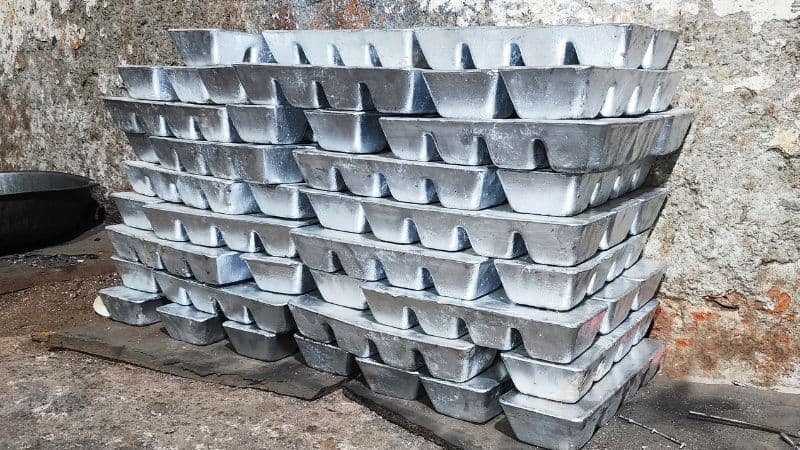
Aluminum Die Casting Tolerances
Aluminum die casting offers good dimensional control, especially for medium to large production runs. Standard NADCA tolerances for aluminum often range from ±0.002 in/in (±0.05 mm/25 mm) for linear dimensions, with a minimum limit around ±0.005 in (±0.13 mm) for small features.
Flatness and straightness tolerances depend on part size and geometry. Larger castings may allow slightly looser tolerances due to thermal contraction during cooling.
Aluminum die casting service providers often reference NADCA tables to set limits for:
| Feature Type | Typical Tolerance (Aluminum) |
|---|---|
| Linear (per inch) | ±0.002 in (±0.05 mm) |
| Hole Diameter | ±0.003 in (±0.08 mm) |
| Flatness (per inch) | ±0.004 in (±0.10 mm) |
These tolerances generally exceed those achievable by sand casting or investment casting without machining.
Zinc and Magnesium Die Casting Tolerances
Zinc die casting can achieve tighter tolerances than aluminum due to its lower shrinkage rate and higher dimensional stability. Typical linear tolerances for zinc are about ±0.0015 in/in (±0.038 mm/25 mm), with small features often holding ±0.002 in (±0.05 mm).
Magnesium die casting tolerances fall between aluminum and zinc. Magnesium offers good stability but may require slightly looser limits for thin-walled designs.
Zinc’s low melting point allows longer tool life and consistent dimensions over high-volume runs. This makes it well-suited for small, precise components such as gears, housings, and connectors.
| Feature Type | Typical Tolerance (Zinc) |
|---|---|
| Linear (per inch) | ±0.0015 in (±0.038 mm) |
| Hole Diameter | ±0.002 in (±0.05 mm) |
| Parting Line Shift | ±0.002 in (±0.05 mm) |
Tolerance Comparison by Casting Process
Different casting processes produce different tolerance ranges. Die casting generally achieves the tightest tolerances without secondary machining.
Typical tolerance capability (per inch):
| Process | Typical Linear Tolerance |
|---|---|
| High Pressure Die Casting | ±0.0015–0.004 in (±0.038–0.10 mm) |
| Investment Casting | ±0.005 in (±0.13 mm) |
| Sand Casting | ±0.010 in (±0.25 mm) or greater |
Die casting’s higher precision comes from using hardened steel molds under high pressure. Sand casting uses loose sand molds, which limits repeatability and increases dimensional variation. Investment casting offers better accuracy than sand casting but still requires machining for critical fits.
These differences help determine whether a part should be die cast directly to size or cast oversized and machined to final dimensions.
Quality Assurance and Inspection Methods
Maintaining dimensional accuracy in die cast parts requires both precise measurement and consistent process control. Manufacturers rely on targeted inspection methods, statistical monitoring, and detailed reporting to confirm that parts meet specified tolerances and remain within acceptable variation limits.
Inspection Techniques for Die Cast Parts
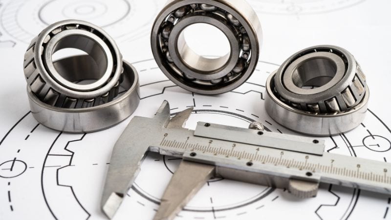
Dimensional checks are typically performed using calipers, micrometers, coordinate measuring machines (CMMs), and optical comparators. These tools verify critical features such as hole diameters, wall thickness, and flatness.
Non-destructive testing methods, like X-ray inspection, detect internal defects such as porosity or voids without damaging the part. Surface defects are identified through visual inspection under controlled lighting.
For complex geometries, 3D scanning can capture full-surface data and compare it directly to CAD models. This helps detect warping, shrinkage, or deviations in less accessible areas.
Inspection frequency often depends on production stage. First-article inspections confirm tooling accuracy, while in-process checks monitor ongoing runs and catch deviations early.
Statistical Process Control in Die Casting
Statistical Process Control (SPC) tracks production data to detect trends before parts fall out of tolerance. Measurements from sample parts are plotted on control charts to monitor variation over time.
Key metrics like Cp (process capability) and Cpk (process capability index) indicate how well the process stays within tolerance limits. Higher values suggest more stable, predictable output.
SPC in die casting often focuses on variables such as melt temperature, injection pressure, and cooling rate. Changes in these parameters can directly affect dimensional accuracy and surface quality.
By identifying shifts early, operators can adjust process settings—such as die temperature or shot speed—before defects occur. This reduces scrap rates and improves consistency across production batches.
Frequently Asked Questions
How do material properties affect tolerance levels in die cast parts?
Different alloys shrink at different rates as they cool, which can alter final dimensions.
Metals with higher thermal expansion may require tighter process control to stay within limits.
Material hardness can also influence how much post-casting machining is needed to meet tolerances.
How does die design impact the precision of cast components?
A well-designed die minimizes distortion and uneven cooling. Proper gating and venting reduce defects that can affect dimensional accuracy. Alignment features in the die help control parting line shifts and maintain repeatability.
Can surface finish affect the tolerances achievable in die casting?
Surface finish can influence how dimensions are measured and interpreted. Rough surfaces may cause variations in readings during inspection. A smoother finish often improves measurement consistency and can reduce secondary machining needs.