When the term EDM (Electrical Discharge Machining) is brought up, it mainly refers to two highly capable processes, sinker EDM and wire EDM. They both remove metal with controlled sparks and excel on hardened, conductive materials. But in practice they serve different kinds of features, require different tooling, and come with distinct trade-offs in setup and finish.
This guide aims to parse sinker EDM vs wire EDM with more clarity on their mechanics, applications, and selection criteria. It will surely help you make the right choice before committing to a certain EDM machining method!
How Sinker EDM and Wire EDM Work
Sinker EDM Machining (Ram EDM)
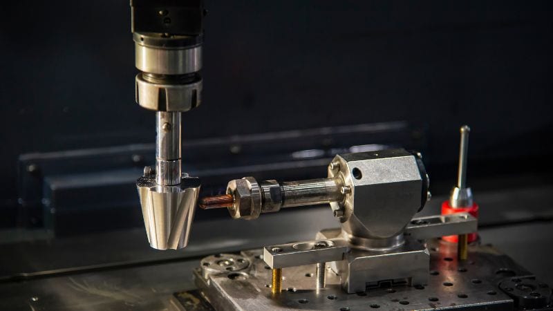
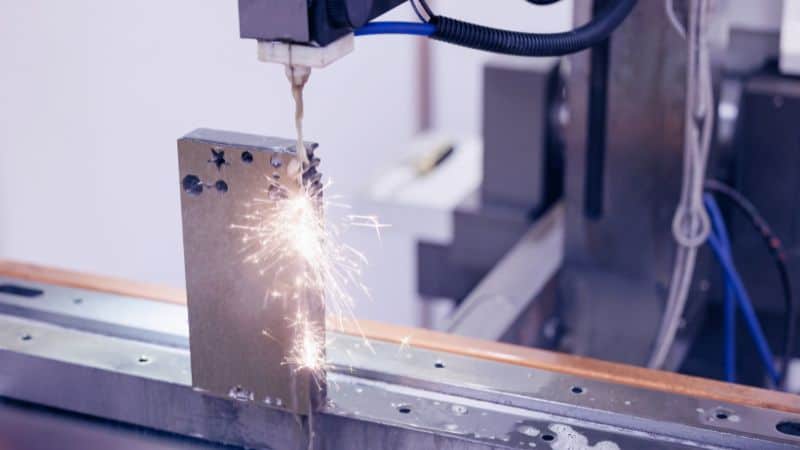
This process plunges a shaped electrode, typically made from graphite or copper, into the workpiece. Both the electrode and the part are submerged in dielectric fluid, which insulates, cools, and flushes away eroded particles. During the EDM process, a series of rapid electrical discharges form on the contact surface between the electrode and the workpiece, which erode material to precisely mirror the electrode’s shape.
Sinker EDM is the preferred method for creating blind features—such as mold cavities, die details, and complex 3D forms—that would be impossible to mill due to tool deflection or poor reach. The primary trade-off is the electrode itself; designing and fabricating custom electrodes, often requiring multiple ones for roughing and finishing, adds to the setup time and cost. However, for deep, high-aspect-ratio features in tough materials like hardened steel, it is often the only reliable solution.
Wire EDM Machining (Electrical Discharge Wire Cutting)
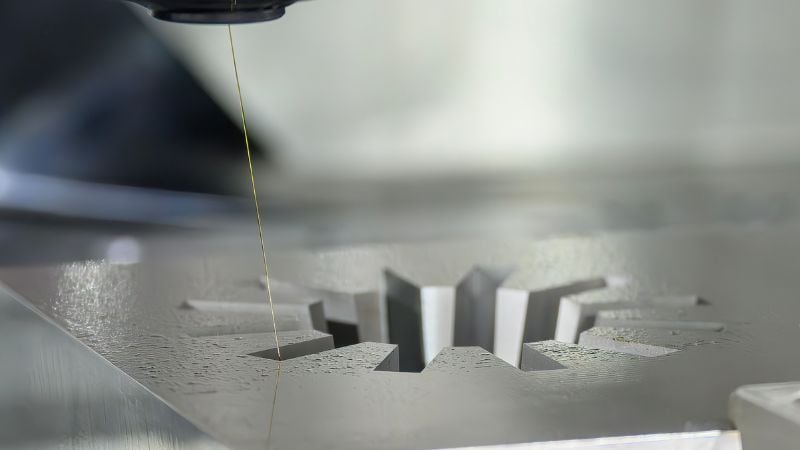
Wire EDM uses a thin wire (often 0.010” in diameter) that is continuously fed as the electrode. The metal wire travels along a programmed path, primarily in the X/Y plane, while upper and lower guides can move independently to cut tapers or complex contours. Since the wire is constantly fed from a spool, a fresh section is always performing the cut, ensuring consistent performance.
This machining process is constrained to through-cuts, requiring a pre-drilled starter hole for any internal features. It is exceptionally fast to program and easy to fixture, making it ideal for producing punches, dies, precision flat parts, and for parting out complex shapes from plates with excellent repeatability and fine surface finishes.
Mechanical Differences Between Sinker EDM and Wire EDM
| Feature | Sinker EDM | Wire EDM |
| Geometry & Access | Excels at blind features like closed-bottom cavities, deep ribs, and internal splines. It requires no through-access. | Limited to through-cuts. Ideal for complex 2D profiles and contours. Requires an exposed edge or a starter hole. |
| Tolerances & Finish | Can achieve tight tolerances (±0.0002–0.001″) | Routinely holds tight tolerances (±0.0001–0.0002″) and delivers fine finishes directly from multiple skim passes. |
| Key Advantage | Creates complex 3D cavities unreachable by other tools. | Highly accurate for 2D contours with minimal setup; the “wire” tool is universal. |
| Materials | Both processes machine a large variety of conductive materials, including hardened tool steel, carbide, and exotic alloys, without being affected by hardness. | |
Minimum Radii and Corner Detail
Wire EDM delivers extremely tight inside corners and fine details, limited primarily by wire diameter and corner control. Use smaller wire (e.g., 0.006–0.004 in) and multiple skim passes when ultra-fine fillets are required.
Sinker EDM‘s smallest features depend on electrode geometry and rigidity: finer tips are possible, but they’re more fragile and slower to burn. For razor-sharp punch profiles or delicate slots, wire is typically the cleaner choice.
Draft, Depth, and Aspect Ratio
Sinker EDM can deal with various depths. High aspect ratio ribs, deep pockets, and tall walls with minimal draft are routine in sinker EDM process, assuming appropriate flushing and staged electrodes.
Wire EDM is constrained by maximum machine Z (workpiece height) and access: while it can taper and cut tall sections, extreme depth or features without through-access are not feasible. If the design demands deep, closed-bottom geometry, lean sinker.
Heat-Affected Zone, Recast Layer, and Stress
Both processes create a thin recast layer and heat-affected zone from spark erosion. Typically, there’s minimal residual stress because there’s no tool pressure. Finishing passes, optimized parameters, and post-process polishing or etching can reduce recast to meet demanding aerospace or medical specs.
Speed & Cost Differences Between Wire EDM and Sinker EDM
Setup and Fixturing
Wire EDM shines in setup efficiency. Parts can be clamped simply, and programming is straightforward. The only caveat is access: a starter hole is needed for internal profiles. For batches of identical 2D shapes, wire is exceptionally consistent and economical.
Sinker EDM‘s setup is dominated by electrode strategy. Time and cost lie in designing, machining, and qualifying electrodes, along with verifying burn parameters. Fixturing is flexible, and, critically, the process can start at any point on the surface. For deep, complex cavities where milling struggles, sinker often pays back its upfront cost by producing features that would otherwise be impractical.
Electrode and Wire Consumption
Wire EDM consumes wire continuously: consumables are predictable and scale with cut length and thickness.
Sinker EDM consumes electrodes, sometimes multiple per feature. Electrode wear and duplication for finishing passes can represent a significant share of total job cost. In quoting sinker EDM, electrode count and complexity are major levers.
Automation Potential
Modern wire and sinker EDM platforms support robust automation: tool changers, palletized workholding, and reliable unattended operation. Wire EDM is particularly well-suited to lights-out for stacked plates or nested parts: sinker EDM can also run unattended with multiple queued electrodes and in-machine measurement, provided the burn plan is validated.
Respective Application Scenarios
Applications of Sinker EDM
Cores and cavities, ejector pockets, conformal features, deep ribs, and internal splines of die casting mold point to sinker EDM. It also complements hard milling when reach, tool deflection, or tiny radii make mechanical cutting risky or impossible. If the feature is blind or fundamentally 3D with varying depths, sinker EDM provides the necessary control.
Applications of Wire EDM
Wire EDM dominates on through profiles: punches and dies, gears and sprockets, surgical instrument blanks, EDM-ing out inserts, and parting precision flat components from plate. Expect tight tolerances, repeatability across batches, and excellent edge quality, often straight off the machine after skim passes.
Integrated Workflows
Complex tools often benefit from both. For example, wire EDM can rough out internal slots or remove bulk material to reduce sinker burn time. Sinker EDM then finishes fine 3D details and blind features. This hybrid approach shortens cycle time, reduces electrode count, and improves overall economics.
Practical Selection Checklist
Questions to Ask Before Choosing
- Is the feature a through-cut or a blind cavity?
- What tolerance and surface finish are required on functional surfaces?
- What is the material and thickness/part height?
- Are there extremely small inside radii or sharp corners?
- What’s the production volume and repeatability requirement?
- Are there access constraints (need for a starter hole or no external edge)?
Data To Provide To Your EDM Manufacturer
- 3D CAD (and 2D drawings with GD&T) clearly marking EDM features
- Material specification and hardness/condition
- Part thickness/height and any taper requirements
- Target tolerances and surface finish callouts per surface
- Feature intent: blind cavities vs through-cuts: minimum radii
- Quantity, delivery targets, and any lights-out or automation preferences
Conclusion: Is There a “Better” EDM Machining Method?
This is not a simple yes-or-no question, and a more reasonable answer would be “choose the right tool for the specific job.” Sinker EDM excels at complex 3D cavities and blind features, while wire EDM is unparalleled for precision through-cut profiles. The optimal choice is ultimately dictated by a wide range of criteria.
Frequently Asked Questions
Are there compatibility issues with coatings, platings, or subsequent surface treatments?
EDM introduces a thin recast layer that can affect adhesion or diffusion of coatings/platings; manufacturers can remove or minimize it with surface finishes like finishing burns or light grinding/polishing. If you plan post-process heat treatment, state it up front—manufacturers may adjust burn parameters or schedule EDM after heat treatment to avoid recast/softening conflicts.
What are common causes of wire EDM wire breakage, and how are they mitigated?
There are many possible reasons for breakage: improper flushing, excessive spark energy for the section, wire tension or guide misalignment, abrasive inclusions in material, aggressive cornering, etc.
To prevent the delicate wire from snapping, manufacturers often adopt optimized flushing paths, lower energy passes near critical features, multi-pass strategies, tighter fixturing, and so on.
How should fragile or thin sections be fixtured for EDM?
Use segmented supports, sacrificial backing plates, soft clamps that distribute load, and staged cutting strategies (pre-rough with lower energy). For very thin/fragile parts, manufacturers may recommend bonding to a carrier plate or stacking/nesting to reduce distortion and to enable