Die cast tooling, as its name suggests, encompasses molds and dies of the die casting process. When it’s engineered well, it delivers crisp features, tight tolerances, and stable cycle times across hundreds of thousands, sometimes millions, of shots.
In this article, we at Moldie will extract the essentials of die cast tooling, and help you gain a better insight into its operation mechanism, tooling solutions, and other factors that are relevant in die casting technology.
What Is Die Cast Tooling and How Does It Work
At its core, die cast tooling is a complex, high-strength steel mold comprised of two or more halves. Its primary function is to shape molten metal under immense pressure into a net-shape part.
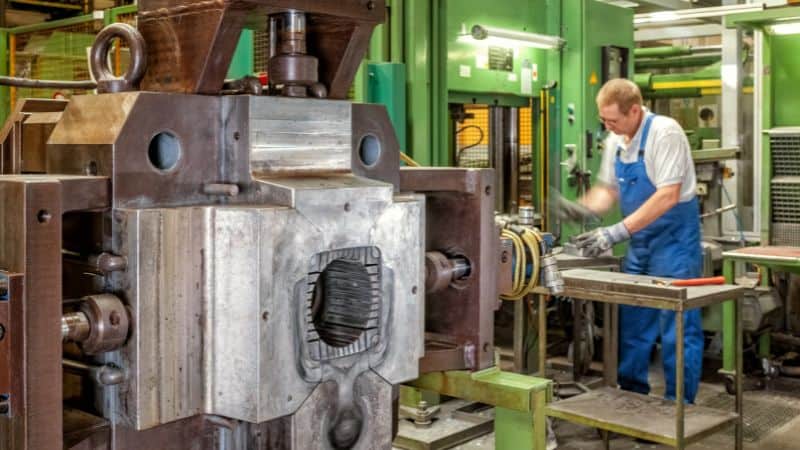
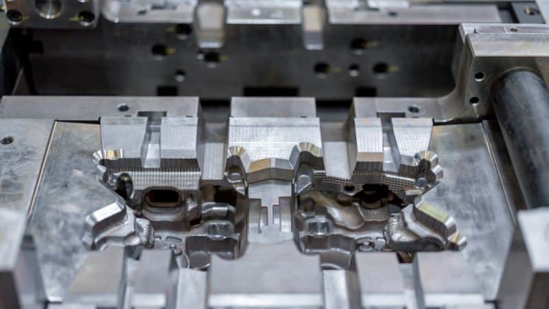
A standard die casting tool consists of two main halves:
- The Cover Die (Fixed Half): This half is mounted to the fixed platen of the die casting machine and contains the injection system—either the gooseneck (in hot-chamber) or the shot sleeve (in cold-chamber).
- The Ejector Die (Moving Half): This half is mounted to the moving platen and contains the ejection system to push the solidified casting out after the cycle.
The Die Casting Cycle in Four Key Steps:
-
Clamping: The two halves of the die are hydraulically clamped together with immense force (often hundreds to thousands of tons) to withstand the high pressure of injection.
-
Injection: Molten metal is injected into the die cavity at high speed and pressure. This is where the distinction between hot chamber and cold chamber systems becomes critical, as detailed in the next section.
-
Cooling: The metal solidifies inside the cavity, taking its final shape. The tooling is equipped with intricate internal cooling channels that circulate water or oil to control the solidification process and manage the extreme thermal cycles.
-
Ejection: The clamp opens, and the ejector plate in the moving half advances, pushing ejector pins against the casting to release it from the die.
This cycle repeats every few seconds for the life of the tool, subjecting it to extreme thermal stress (from molten metal), mechanical stress (from clamping and injection pressure), and abrasive wear. The design, materials, and maintenance of the tooling are all optimized to survive this harsh environment.
Custom Mold Design for Die Casting Tooling
Draft, Radii, and Wall Thickness
Applying adequate draft is the first step to clean ejects and longer service life. For optimal results, use a draft angle of 0.5 to 1.0 degrees on exterior faces and a slightly steeper 1.0 to 2.0 degrees on interior cores. Also, if the surface is textured, you will need to add even more draft, typically an extra degree or more, to accommodate the it and prevent the part from sticking during ejection.
Beyond draft angles, incorporating generous fillets is critical for the part’s durability and quality. Using fillets with a radius of at least 0.5 to 1.0 mm for zinc, and 1.0 to 2.0 mm for aluminum helps to distribute stress and prevents cracking by reducing sharp corners. This procedure also improves the flow of molten metal.
Furthermore, designs should maintain uniform wall thickness, use strategic ribs and bosses and avoid extremely thin walls—generally staying above 0.8 to 1.0 mm for aluminum—unless the specific setup is proven to handle them.
Tolerances and Critical Datums
Establish a clear datum reference frame using sturdy, accessible surfaces that are critical to the part’s function and measurement. Apply Geometric Dimensioning and Tolerancing (GD&T) to control form, orientation, and location—such as flatness, position, and profile. This system defines the part’s functional limits. Avoid over-constraining the design by allowing looser tolerances on non-critical surfaces, which simplifies tooling and manufacturing without affecting performance.
Datum targets must be placed on stable, as-cast pads that are easily accessible to probes. Never define a target across the parting line, as slight misalignments between mold halves will cause measurement errors and compromise the reference frame.
Remember that as-cast tolerances are wider than machined ones. Apply machining allowances only to critical features like sealing surfaces or bearing fits, leaving other areas as-cast. This minimizes secondary operations and reduces cost.
Parting Strategy, Slide Minimization, and Cost
The cost and complexity of die cast dies are primarily driven by their parting line and slide count. Since every slide adds significant expense, maintenance, and time, a key design goal is to minimize them. This can be done by reorienting features to the main parting plane or redesigning to remove undercuts. The best approach is early collaboration and DFM analysis, which can consolidate slides, shorten lead times, reduce costs, and enhance tool durability.
Textures and Logos
Designing textures and logos requires specific steps to ensure quality and durability. Applying any texture demands increased draft angles for proper ejection, so always consult your supplier for their exact specifications when adding logos. Whenever possible, logos should be positioned on non-critical, non-functional surfaces. They are best recessed into the surface, rather than raised, to prevent scuffing and wear on the tool.
Tool Steel Materials and Surface Treatments
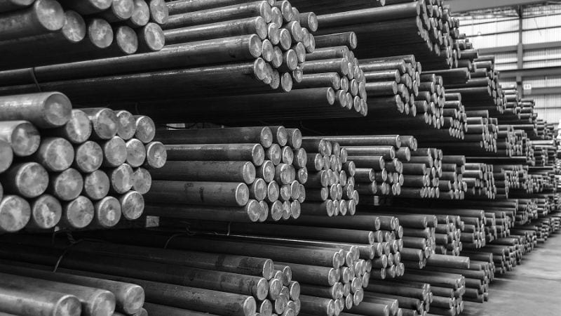
Common Tool Steels (H13, H11, Maraging)
- H13: The industry workhorse for aluminum die casting, with good hot strength, thermal fatigue resistance, and toughness. Proper heat treatment and tempering are non-negotiable.
- H11: Offers good toughness and thermal shock resistance but is less commonly used than H13 for major cavities and cores in aluminum die casting due to its lower hot strength.
- Maraging steels: Useful for inserts requiring high strength and excellent machinability or for hybrid additive-manufactured inserts; typically paired with surface engineering to mitigate soldering.
Other common steels include P20 for zinc and magnesium alloys, and high-hardness steels like D2 for ejector pins and other high-wear components.
Coatings, Nitriding, and Surface Engineering
- Nitriding: Builds a hard, wear-resistant diffusion layer to resist erosion and micro-soldering. It’s widely used on H13/H11.
- PVD/CVD coatings (e.g., TiN, CrN, AlCrN): Reduce wetting, improve lubricity, and limit soldering. Selection depends on alloy and operating temperature.
- Hard chrome, nickel-boron, and specialty anti-solder platings: Applied to gate areas, high-velocity impingement zones, and cores prone to sticking. Surface prep and base steel quality determine success.
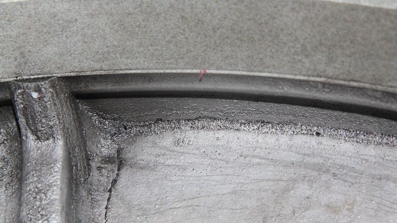
Thermal Fatigue, Soldering, and Erosion Resistance
- Thermal fatigue manifests as heat checking on the die surface caused by rapid cyclic heating and cooling. Mitigation strategies primarily involve using tool steels with high thermal fatigue resistance (like H13) and designing balanced cooling systems to manage the extreme thermal cycles. Preheating the die before production is a critical preventive measure to reduce initial thermal shock.
- Soldering, the undesirable sticking of molten alloy to the die steel, is exacerbated when local steel temperatures dip into a “tacky” range. This can be countered through specialized coatings, release agents, and carefully controlling die wall temperatures to avoid this critical range.
- Erosion typically appears near gates or areas with sharp flow turns, where high-velocity molten metal impinges on the surface. To combat this, impact angles should be softened, radii increased, and surfaces in these critical zones can be locally hardened for greater resistance.
Building, Sampling, And Maintaining The Tooling
Toolmaking Workflow and Lead Times
A typical die cast tooling program normally runs through 8 steps:
First Article, Tryouts, and Iterations
Initial sampling verifies fill, porosity, and dimensional stability. Expect to iterate on gate sizes, vent depths, spray recipes, and shot parameters. The first article inspection ties measured results to the drawing’s GD&T. Data-driven loops, thermal imaging, cavity pressure traces, and vacuum levels help converge faster than guesswork.
Preventive Maintenance, Refurbishment, and Repair
Routine PM includes cleaning vents, refurbishing shut-offs, verifying ejection wear, and reseating coolant fittings. Re-nitriding and spot weld repairs extend life. Keep a spare-insert strategy for high-wear cores and gate areas. Track cycles-to-maintenance and defect modes: tools speak through their wear patterns.
Common Defects and Remedies
Porosity, Cold Shuts, and Misruns
- Gas porosity: Improve venting/vacuum, reduce turbulence via gate geometry, and stabilize die temperature. Rebalance spray and lube to avoid trapped vapors.
- Shrink porosity: Thicken local sections or add feeds/overflows; adjust cooling to avoid premature freeze in hot spots.
- Cold shuts/misruns: Raise melt and die temperatures within spec, enlarge gates, or reposition them to keep the flow front hot and continuous.
Flash, Soldering, And Sticking
- Flash: Improve shut-off flats, correct die lock, and verify clamp force. Excessive spray can also cause hydraulic wedging.
- Soldering: Increase steel surface temperature above sticking range, apply anti-solder coatings, and tweak lube chemistry. Reduce direct impingement by re-aiming gates.
- Sticking: Add draft, polish ejection surfaces, redistribute ejector pins, or switch to ejector sleeves where bosses are tall.
Warpage and Dimensional Drift
- Warpage: It stems from uneven cooling and residual stress. Balance cooling circuits, use conformal channels on asymmetric parts, and temper process parameters for gradual solidification.
- Dimensional drift: This may happen over long runs, signaling thermal growth of the die. For stubborn features, design in post-cast calibration or targeted finish machining.
Conclusion
Die cast tooling is a vital investment that ensures quality and efficiency through precision engineering and strategic collaboration. You should choose partners with well-established mold production process and extensive experience in DFM. This approach transforms challenges into reliable production, delivering consistent value and a competitive advantage.
Frequently Asked Questions
How does part complexity actually translate to higher tooling cost? Is it just about size?
While part size influences steel cost, there is much more to the cost of tooling than just the amount of material used. Each undercut requiring a slide, each complex core, and every tight-tolerance feature adds engineering time, precision machining, and future maintenance points. A simpler part with a clean parting line and low production volume can often be run in a less expensive, more reliable single-cavity tool. A part with many undercuts will require a complex multi-slide tool, regardless of cavitation.
What are the key indicators during a tool sampling/tryout phase that predict future production problems?
We suggest you watch for consistency. If minor adjustments to machine parameters (like temperature or injection speed) cause major swings in part quality or defects, the tool design may be unstable. Other red flags include difficulty ejecting parts consistently, signs of soldering on initial shots, or the inability to establish a wide, stable “process window” where good parts are produced. A qualified tool should be forgiving and repeatable.
When is it more cost-effective to design a “simpler” tool and use secondary machining for complex features?
This approach is often wise for features that are extremely difficult or expensive to cast, such as very deep, small-diameter holes, threads with pristine roots, or extremely sharp internal corners. By casting a solid block and drilling/tapping it in a secondary operation, you avoid the cost and potential failure points of fragile core pins in the mold. It’s a trade-off between per-part machining cost and initial tool complexity/risk.