


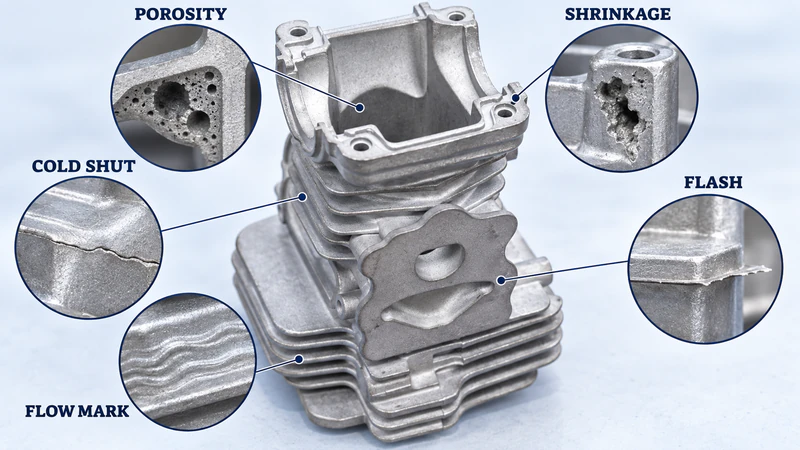
High pressure die casting (HPDC) produces thin-wall aluminum, zinc and magnesium parts at high speed and with repeatable dimensions. The same fast filling, however, leaves little time for air to escape or for a cold flow front to recover. When mold design, melt preparation, temperature control and shot settings are not balanced, the result can be HPDC defects such as porosity, shrinkage, cold shuts, flash and flow marks.
For a mold engineer or buyer, the key questions are where the defect formed, when it appeared and which process step could have created it. This prevents random parameter changes and leads to a more stable die.

What Are HPDC Defects?
HPDC defects are deviations from the required geometry, surface quality or internal integrity of a die-cast part. They can be grouped into four practical families:
- Filling defects: misruns, short shots, cold shuts and flow marks caused by a cold or unbalanced metal front.
- Solidification defects: gas porosity, shrinkage porosity, sinks and hot spots created as the casting freezes.
- Tooling and pressure defects: flash, soldering, drag marks and dimensional drift related to parting surfaces, alignment, ejection or excessive die temperature.
- Cleanliness defects: inclusions, blisters and stains linked to oxides, moisture, release agent or contaminated metal.
Moldiecasting’s overview of the pressure die casting process explains why the cavity can fill in milliseconds and why vents, overflows, gates and cooling must be designed as one system.
The Most Common HPDC Defects
1. Porosity
Porosity is a void inside or close to the surface of the casting. Gas porosity is usually smooth and rounded, formed when air is trapped by turbulent filling or cannot escape through the vent and overflow system. Hydrogen and moisture in the melt can create similar rounded pores. Shrinkage porosity is more irregular and often appears in thick bosses, rib intersections or other last-to-freeze areas where liquid metal cannot feed the contracting material.
Typical corrections include cleaning or enlarging vents, relocating overflows, reducing turbulence, stabilizing the shot profile, drying release agent and tools, degassing the melt, and balancing cooling. Vacuum can further reduce cavity air for leak-tight or structural parts, but it cannot compensate for a blocked vent or poorly balanced runner. See Moldiecasting’s guide to die casting defects and solutions for a broader troubleshooting reference.
2. Shrinkage and Sink Marks
Shrinkage occurs when a hot spot solidifies after surrounding metal has already frozen. The defect may remain internal or appear as a surface depression called a sink mark. Uneven wall thickness, a heavy boss, a gate that freezes too early, low holding pressure or insufficient cooling are common contributors.
The solution starts with geometry: keep walls as uniform as practical, use generous radii and core out heavy sections. In the die, direct cooling toward hot spots without creating a severe thermal gradient. Then verify intensification timing and pressure so the gate remains open long enough to feed the last-freezing region.
3. Cold Shuts and Cold Laps
A cold shut is a visible line or seam where two metal fronts meet but do not fuse. A cold lap is a related overlap that can create a weak, layered interface. Both defects are more likely when the metal or die is too cold, the flow path is too long, the injection speed is too low, or the gate layout makes the fronts meet after excessive heat loss.
Raise melt or die temperature only within the alloy and tooling window. Also review gate location, runner balance, fast-shot velocity and venting at the meeting point. Enlarging a gate may help, but an uncontrolled increase in speed can create turbulence and new porosity, so the complete fill pattern should be checked with simulation or a controlled trial.
4. Flash
Flash is a thin, unwanted fin of metal along a parting line, slide, ejector or insert. It indicates that metal is escaping through a gap under injection pressure. Excessive pressure or intensification, insufficient clamp force, die misalignment, worn shut-offs and thermal distortion can all contribute. Heavy spray can also create a hydraulic wedge between die halves.
First inspect the parting line and shut-off surfaces for wear, damage or trapped debris. Confirm die alignment and clamp force, then review pressure only after the tooling condition is known. Reworking a worn shut-off is usually more durable than repeatedly trimming flash after casting.
5. Flow Marks and Swirl Marks
Flow marks are wavy lines, bands or color changes that reveal an irregular metal front. They often result from a cold die, unstable injection speed, an abrupt change in wall thickness, poor gate positioning or uneven release-agent coverage. The marks may be cosmetic, but they can also signal a filling pattern that folds air or creates a cold shut elsewhere.
Use a balanced gate and runner, keep the die at a stable operating temperature, and tune slow-shot to fast-shot transition rather than simply increasing pressure. Consistent spray quantity and drying matter because wet lubricant can cool the surface and generate gas.
6. Misruns, Short Shots and Other Defects
A misrun or short shot occurs when the metal freezes before the cavity is completely filled. Look for insufficient shot volume, low melt or die temperature, poor gate access, slow fill or a vented pocket that is actually sealed. Other defects include soldering, where alloy sticks to hot die steel; drag marks caused by inadequate draft or rough ejection surfaces; inclusions from oxides or dross; and blisters caused by near-surface gas that expands during heating.
HPDC Defect Diagnosis Table
The following table is a practical first-pass screen. It is not a substitute for CT, X-ray, sectioning, leak testing or a documented acceptance standard when the part is safety- or pressure-critical.
| Defect | Visual or inspection clue | Likely root causes | First corrective action |
| Gas porosity | Smooth round pores, often near last fill | Poor venting, turbulent fill, moisture, excess spray | Clean vents and overflows; check vacuum, shot profile and spray drying |
| Shrinkage porosity or sink | Irregular cavity or surface depression in thick area | Hot spot, early gate freeze, weak feeding, low hold | Balance cooling; review wall thickness, gate freeze and intensification |
| Cold shut or cold lap | Line where two fronts meet without bonding | Low melt/die temperature, long flow path, slow fill, poor gate position | Stabilize temperatures; review gate location and fill speed |
| Flash | Thin fin at parting line, slide or ejector | Worn shut-off, misalignment, low clamp force, excessive pressure | Inspect tooling and alignment; verify clamp force before changing pressure |
| Flow mark | Wavy band or color change following flow | Unstable front, cold die, uneven spray, poor gating | Tune transition and gate balance; stabilize die temperature and spray |
| Misrun or short shot | Missing edge, rib or end-of-fill section | Insufficient metal, low temperature, slow fill, trapped air | Check shot volume, temperature, gate access and end-of-fill venting |
Preventing HPDC Defects Through Mold Design
Prevention is cheaper than sorting. During design review, verify uniform wall transitions, suitable draft and radii, balanced runners, a gate that fills the cavity progressively, and overflows at the last-fill locations. Venting should cover deep cores, slides and blind pockets, while cooling channels should remove heat from bosses and thick intersections without freezing the gate prematurely.

Moldiecasting’s die casting mold design guidance and die cast tooling best practices emphasize flow simulation, shut-off quality, cooling balance and maintenance access before steel is cut. These decisions have a direct effect on scrap rate, cycle consistency and tool life.
A Repeatable Troubleshooting Method
When a defect appears, record the cavity, location, alloy batch, die and melt temperatures, spray cycle, shot profile and actual pressure. Defects that move around often indicate unstable temperature, coolant flow, lubrication or machine settings. Change one variable at a time and confirm the result with the required inspection method.
The most reliable HPDC process is a closed loop: design the flow path, prepare clean metal, stabilize the thermal cycle, verify the part and feed the evidence back into the process plan.
Work with Moldiecasting on HPDC Defect Prevention
Moldiecasting supports custom die casting molds and cast parts in aluminum, zinc and magnesium, with engineering input on gating, venting, cooling, materials and production parameters. If your project is experiencing recurring porosity, cold shuts, flash, flow marks or incomplete filling, contact us for a practical review of the part geometry, mold design and process window.