


High pressure die casting is built for repeatable production, but the die itself works under an unusually severe combination of heat, pressure, velocity and thermal cycling. Every shot exposes the cavity, core, gates and slides to molten metal, rapid solidification, ejection and cooling. Over time, the tool may develop heat checking, erosion, soldering, distortion or cracking. When that happens, the issue is not only the cost of a repair. It can also affect surface finish, dimensions, cycle time, scrap rate and delivery performance.
For buyers and engineers, HPDC mold life means more than a target number of shots. It is the period during which a die keeps producing acceptable parts within a stable process window. Four connected decisions shape it: die steel, heat treatment, mold temperature and cooling, and production parameters.
What Does HPDC Mold Life Mean?
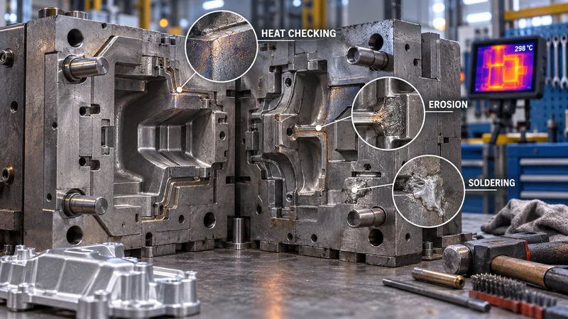
HPDC mold life is the effective service life of a die before cracks, wear, deformation or quality drift make production uneconomical. A die can still open and close while producing flash, dimensional variation, soldering marks or inconsistent filling.
The most common failure modes are thermal fatigue, erosion, corrosion or soldering, indentation and mechanical cracking. Thermal fatigue, often seen as fine heat-checking cracks, is especially important in aluminum and magnesium work because the die surface is repeatedly heated by the melt and cooled by sprays or internal channels. A sound estimate must consider the alloy, geometry, production rate, process control, steel and heat treatment together.
Factor One: Die Steel Selection
Die steel sets the material performance ceiling, but the best grade depends on the alloy and thermal load.
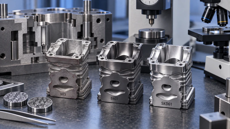
H13, DIN 1.2344 and SKD61 are widely used hot-work steels for HPDC cavities, cores and inserts. They offer a useful balance of hot strength, toughness, machinability and resistance to thermal fatigue. For high-volume aluminum programs, thin-wall parts or areas with severe hot spots, premium grades such as 8407 or Dievar may be considered when their higher cleanliness and toughness justify the tooling investment.
The alloy also matters. Zinc is processed at a lower temperature and is generally less aggressive to the die than aluminum. Aluminum creates a higher thermal load and can promote erosion, soldering and heat checking. Magnesium requires its own balance of temperature control, toughness and wear resistance. Moldiecasting’s die casting mold information lists Dievar, H13, 8407 and 1.2344 among the insert materials that can be specified for customer requirements.
P20 and NAK80 should not be treated as automatic substitutes for hot-work steel in a long-running production die. They may be suitable for prototypes or short validation runs, but sustained HPDC thermal cycling demands a material selected for hot strength, toughness and heat-checking resistance.
Factor Two: Heat Treatment Quality
Heat treatment determines whether the selected steel can deliver its intended combination of hardness and toughness. Hardening establishes the base strength. Tempering reduces quench stresses and restores toughness. The objective is not simply to obtain the highest possible hardness; an overly brittle insert can crack, while an under-hardened surface can wear, erode or deform.
Key controls include uniform heating, a controlled quench, sufficient tempering and dimensional checks. Large inserts and complex cores require attention to distortion and microstructural uniformity. After rough machining, EDM or major repair work, a suitable stress-relief step can reduce the effect of residual stress during production.
Surface engineering can support the base treatment. Nitriding may improve surface hardness and wear resistance, while a suitable PVD coating can help reduce soldering and improve release in selected applications. These treatments cannot compensate for poor steel cleanliness, inadequate toughness or an unstable thermal process, and the layer properties must be matched to the alloy and operating conditions.
Factor Three: Mold Temperature and Cooling
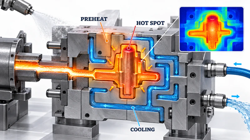
Temperature control is often the most direct way to influence thermal fatigue. The die needs enough preheat for stable filling and a controlled operating temperature, but it must also avoid excessive surface temperature and large temperature gradients.
If the die is too cold when the first shots begin, the temperature difference between the melt and the steel increases thermal shock and may contribute to cold shuts or early heat checking. If the surface becomes too hot, the steel may soften, soldering may increase and the thermal fatigue cycle becomes more severe. The correct window depends on the alloy, wall thickness, shot profile, lubricant and cycle time; one universal mold-temperature number is not appropriate for every tool.
Cooling channels should remove heat consistently rather than simply as fast as possible. Channels that are too far from the cavity can leave hot spots, while aggressive local cooling can create steep temperature differences. Balanced flow, clean circuits and stable coolant temperature are more valuable than a nominally low mold temperature. Deep cores and thick sections may require separate thermal management or high-conductivity inserts.
Factor Four: Production Parameters
Even a premium die can fail early if the process window is too aggressive or unstable.
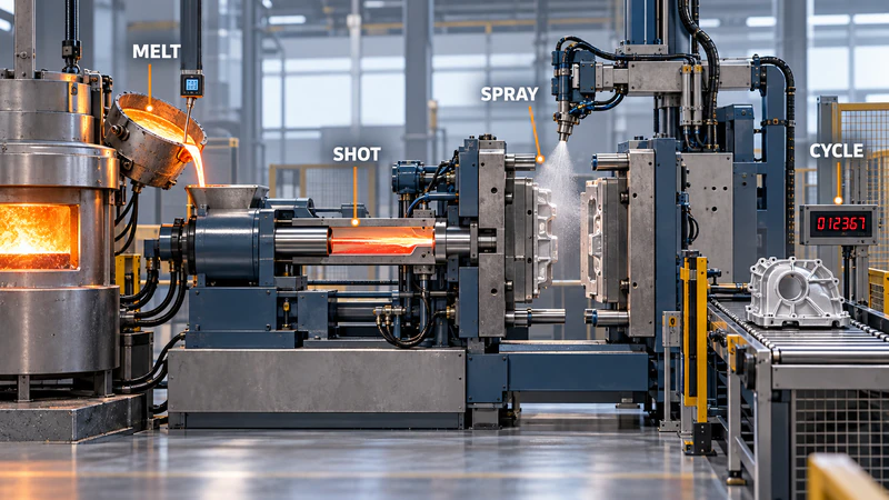
Melt temperature. Excessive melt temperature increases heat input, soldering risk and softening of the die surface. Too little temperature can cause cold shuts and incomplete filling. The target should be established for the alloy, part wall thickness and filling distance.
Fill speed and intensification pressure. High speed is useful for thin walls, but molten metal at the gate and runner can accelerate erosion. Excessive pressure increases mechanical loading on the cavity, parting line and slides. The velocity profile, changeover point and intensification stage should be matched to the gating and venting design.
Cooling and spray. Too little spray can increase sticking and ejection load. Too much spray or an overly cold spray can create thermal shock and unstable cycle temperatures. Cooling time should be long enough for safe ejection without turning the die into a repeated over-cooling and reheating cycle.
Cycle consistency. Long stoppages, rapid restarts and frequent parameter changes can be as damaging as a high nominal setting. Record the actual melt temperature, die temperature, coolant condition, shot profile and cycle time instead of relying only on machine setpoints.
How to Monitor and Extend Die Life
A practical die-life program combines process data with scheduled tool care. Track shot count, repairs, polishing, insert changes and recurring defects. Check gates, runners, overflows, vents, slides and ejector areas for wear or soldering. Look for heat-checking lines and matching finish changes on the casting.
Keep cooling circuits clean and verify their flow and temperature. Remove buildup before it changes the thermal balance. After EDM, welding or grinding, use the appropriate finishing and stress-control procedure. Planned maintenance is usually less expensive than waiting for a crack to spread into a major insert or shut down production.
How Many Shots Can an HPDC Mold Produce?
There is no universal service-life guarantee. As an indicative reference, published hot-work tooling guidance places typical ranges around 500,000 to 2,000,000 shots for zinc, 100,000 to 400,000 for magnesium, and 60,000 to 200,000 for aluminum. These figures are broad benchmarks, not a quotation. Actual life changes with the alloy temperature, cavity geometry, steel, heat treatment, cooling layout, process control and the customer’s acceptance criteria.
Indicative HPDC die-life ranges
| Casting alloy | Indicative range | Typical limiting factors |
| Zinc | 500,000–2,000,000 shots | Erosion and wear |
| Magnesium | 100,000–400,000 shots | Heat fatigue, cracking and erosion |
| Aluminum | 60,000–200,000 shots | Heat fatigue, soldering, cracking and indentation |
Start Your HPDC Mold Life Program with Moldiecasting
Moldiecasting has supplied die casting molds and parts since 2008, working mainly with aluminum, magnesium and Zamak and offering materials such as Dievar, H13, 8407 and 1.2344. To evaluate an HPDC mold, prepare the part drawing or 3D model, alloy, annual volume, critical tolerances, surface requirements, target cycle time and expected service life.
If you are planning a new high pressure die casting project or trying to improve the life of an existing tool, contact us for a tooling and process review covering steel grade, heat treatment, cooling layout and machine suitability.