


High pressure die casting is valued for fast cycles, thin walls and repeatable dimensions, but the same high-speed filling that makes HPDC productive can also trap air inside the casting. The result is HPDC porosity: internal or near-surface voids that may reduce pressure tightness, mechanical strength, fatigue life and machining yield.
For a mold engineer, porosity is rarely solved by changing one machine setting. The root cause may be a blocked vent, an unbalanced runner, excessive turbulence, wet release agent, hydrogen in the melt, or a hot spot in the part. The most reliable approach is to identify the pore mechanism first, then coordinate mold design, metal preparation, thermal control and shot parameters.
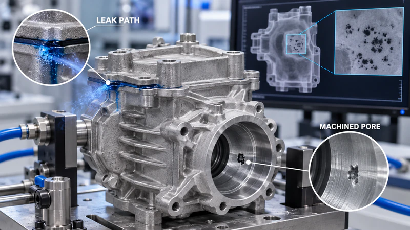
Why HPDC Porosity Matters in Real Products
Porosity is especially important in housings, brackets, gearbox covers, pump bodies and other parts that must remain sealed or retain strength after machining. A pore hidden below the as-cast surface can open during drilling or milling. Gas inside a casting can also expand during coating or heat treatment and create blisters. For structural parts, connected pores reduce the effective load-bearing area and make fatigue performance less predictable.
The goal is not always to achieve zero pores. It is to keep pore size, location and distribution within the acceptance limits for the part. A cosmetic cover and a pressure-tight valve body do not require the same internal-quality target.
What Is HPDC Porosity?
HPDC porosity refers to voids formed when gas remains in the metal, when dissolved hydrogen comes out of solution, or when liquid metal cannot feed a region that is shrinking during solidification. These mechanisms can look similar on a rejected part, but they need different countermeasures.
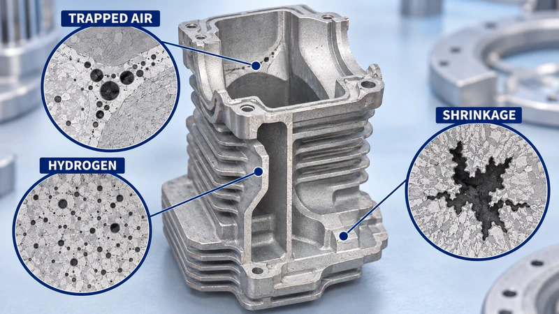
Gas Porosity from Trapped Air
Gas pores are commonly round or oval and may appear near the last-fill area, flow-front meeting points or regions with poor venting. Air can enter from the shot sleeve, be folded into the melt by turbulent flow, or remain in the cavity because vents and overflows cannot discharge it quickly enough. Moisture in die lubricant can add steam to the same problem.
Hydrogen and Moisture-Related Porosity
Aluminum melt can dissolve hydrogen, especially when the metal is overheated or exposed to damp charge material and tools. During solidification, the gas becomes less soluble and forms pores. Inadequate degassing, contaminated returns, wet ladles and excessive spray can all increase the risk.
Shrinkage Porosity
Shrinkage porosity is usually irregular rather than perfectly spherical. It forms when a thick section, boss or rib intersection remains liquid after nearby metal has solidified, but the region is no longer fed by liquid metal. Wall-thickness changes, poor gate location, premature freezing and uneven cooling all contribute.
Main Causes of HPDC Porosity
1. Inadequate Venting, Overflow or Vacuum
The die must remove air ahead of the advancing metal front. Vents that are too small, too short, incorrectly placed or clogged with lubricant and flash create back pressure. If an overflow is not located at the last-fill region, it cannot collect cold metal and displaced air effectively. Deep cores, slides and blind pockets often need additional venting.
Vacuum-assisted die casting can lower the gas content in the cavity before and during filling. It is especially useful for leak-tight, weldable or high-integrity parts, but it still depends on a sealed die, clean vacuum channels and correct valve timing. Vacuum is a process system, not a substitute for sound runner and vent design.
2. Turbulent Filling and an Unstable Shot Profile
Excessive slow-shot speed can push air through the shot sleeve before the fast shot begins. An abrupt changeover, an undersized gate or a jet that strikes a core can break the metal stream and fold air into the casting. Too much intensification pressure may compress an existing gas pocket without removing its source, while also increasing flash, erosion and die loading.
The fill profile should be tuned to the alloy, wall thickness, gate design and machine. Flow simulation can identify where the metal front collides, divides or meets, allowing the mold team to change the gate, runner, overflow or transition point before steel is modified.
3. Poor Melt Cleanliness and Hydrogen Control
Wet or oxidized charge material, long holding time and insufficient degassing make porosity more likely. Aluminum, magnesium and zinc alloys also respond differently to temperature and handling. Stable melt temperature, dry tools, controlled recycling and documented degassing are therefore as important as the die itself.
4. Hot Spots and Insufficient Feeding During Solidification
Thick bosses, deep ribs and abrupt wall transitions cool later than surrounding areas. If the gate freezes too early or the intensification stage begins too late, the shrinking region cannot be supplied. A cooling circuit that is too far from the hot spot has the same effect. The result is shrinkage porosity even when cavity venting is adequate.
5. Unbalanced Mold Temperature and Cooling
A die that starts too cold can freeze the flow front before the cavity is full. A die that runs too hot can increase soldering, soften local steel and leave hot spots. Blocked channels, unstable coolant temperature and excessive local spray create cycle-to-cycle variation that makes pore location unpredictable.
6. Part Geometry That Traps Air or Heat
Closed pockets, sharp internal corners, uneven wall thickness and poorly positioned machining zones make porosity harder to control. A design-for-manufacturability review should consider draft, radii, wall transitions, gate access, overflow placement and the location of critical sealing or machined surfaces.
How to Diagnose the Root Cause
Start with the location, shape and timing of the defect rather than changing pressure immediately.
- Round pores near the last-fill region: Check vents, overflows, vacuum level and fill turbulence.
- Irregular pores in thick sections: Review hot spots, cooling balance, gate freeze time and intensification.
- Blisters after painting or heat treatment: Investigate internal gas porosity, melt hydrogen and moisture.
- Porosity that appears after CNC machining: Compare the machining plane with the internal pore map and move the critical surface if possible.
- Defects that vary from shot to shot: Check spray drying, coolant flow, melt temperature, shot profile and vent cleanliness.
X-ray or CT inspection can reveal internal distribution, while sectioning and metallography help distinguish spherical gas pores from irregular shrinkage cavities. Leak testing is essential for pressure-tight products. Density or melt-quality checks can add evidence, but no single test replaces process data and a clear acceptance standard.
Common Ways to Reduce HPDC Porosity
Improve Mold Flow, Venting and Vacuum
Use balanced runners, a gate that fills the cavity progressively, and overflows at the last-fill zones. Add vent paths for deep cores and slides, then keep them clean during production. If a critical part needs vacuum assistance, verify die sealing, vacuum drawdown, valve timing and the condition of the vacuum channels.
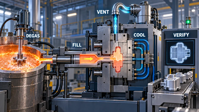
Moldicasting’s die casting mold design guidance emphasizes the role of gates, runners, cooling and metal-flow paths in preventing porosity and dimensional instability.
Tune the Injection and Intensification Profile
Reduce unnecessary turbulence in the slow-shot stage, optimize the slow-to-fast changeover, and match fast-shot velocity to the gate and wall thickness. Set intensification pressure and delay so that pressure reaches the liquid metal before the critical region freezes. Do not treat higher pressure as a universal cure; it can increase die wear when the underlying air-entrapment problem remains.
Improve Melt Preparation
Use dry, clean charge material, remove oxides and dross, and apply an appropriate nitrogen or argon degassing practice. Keep ladles, sleeves and tools dry. Record melt temperature, holding time and melt-quality results so that porosity changes can be connected to a specific batch or shift.
Balance Die Temperature and Cooling
Preheat the die within the alloy-specific process window. Place cooling channels close enough to remove heat from hot spots without creating severe thermal gradients. Verify coolant flow and temperature, and avoid excess spray that produces steam. Thermal simulations and trial data should be used together when the part contains thick bosses or deep cores.
Control Lubricant and Maintenance
Apply only the amount of release agent needed for ejection, then blow the cavity dry. Clean vents, overflows, parting surfaces and vacuum ports before buildup changes the air path. Track pore location against die wear, repairs and maintenance events. This turns porosity control into a repeatable system instead of a series of isolated adjustments.
A Practical Porosity-Control Checklist
Before approving a production die, confirm that the project team has reviewed:
- Product wall thickness, ribs, bosses and critical machining areas
- Gate, runner, overflow and vent locations
- Vacuum requirements and sealing surfaces
- Alloy, melt temperature and degassing method
- Shot profile, intensification timing and cooling cycle
- X-ray, CT, leak-test or sectioning requirements
- Cleaning, spray-drying and preventive-maintenance intervals
Start Your HPDC Porosity Reduction Program with Moldiecasting
Moldiecasting has supplied die casting molds and parts since 2008, supporting aluminum, zinc and magnesium projects. Its engineering team can review product geometry, mold-flow risks, cooling layout and material options such as Dievar, H13, 8407 and 1.2344 before production tooling is finalized. The company’s vacuum die casting guidance also explains when removing cavity air is valuable for lower porosity and higher internal integrity.
If your HPDC project has leakage, machining pores or recurring internal defects, contact us for a mold and process review covering venting, gating, vacuum, cooling and production parameters.