

An HPDC venting system helps determine whether displaced gas escapes or becomes trapped as metal fills the die. Its effectiveness influences internal porosity, filling reliability, and the quality of surfaces exposed during machining. For OEM buyers, venting deserves attention early in mold development, alongside gates, overflows, and cooling.
What Is an HPDC Venting System
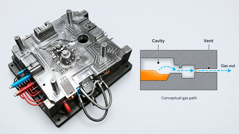
An HPDC venting system provides controlled escape paths for air and process gases displaced as molten metal fills the die. It can include shallow parting line vents, vent blocks, overflow connections, and vacuum channels with valves. In vacuum applications, seals, piping, filters, and controls also influence evacuation.
The gas path must remain connected to the unfilled cavity until evacuation is sufficiently complete. A runner delivers metal and an overflow receives metal; neither automatically provides adequate gas discharge. This guide focuses on cold chamber aluminum die casting molds, with parameters adapted separately for other alloys and processes.
How Venting Affects Gas Porosity
Air can be entrained in the shot sleeve or trapped inside the cavity during rapid filling. Vapor and gases from release agents or plunger lubricants may add to the gas burden. When metal surrounds a gas pocket, subsequent pressure compresses it but does not necessarily remove it from the casting.
Pore appearance provides clues rather than a complete diagnosis. Rounded voids often suggest gas, while irregular cavities in hot spots may suggest shrinkage. Interpret those observations alongside location, process records, and metallurgical examination; a single image or surface indication may not establish the cause.
Gas porosity must be distinguished from shrinkage porosity, which develops as solidifying metal contracts without sufficient feeding. Both mechanisms may occur together. Venting primarily targets displaced air and process gases; it cannot replace melt degassing for dissolved hydrogen or thermal and feeding measures for shrinkage.
How Venting Influences Cavity Filling
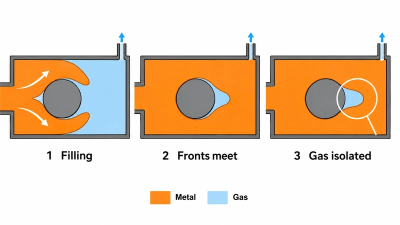
As metal enters, the remaining gas needs to move toward an outlet. Restricted discharge can raise gas pressure ahead of the metal front, increasing resistance in remote or thin regions. If advancing streams close the escape route early, the resulting isolated pocket may persist even with a large vent elsewhere.
Vent placement therefore follows the actual filling sequence. Regions behind cores, meeting fronts, and likely last fill areas deserve particular attention. Gate direction and vent location should work together so the metal advances toward available outlets rather than enclosing gas in critical sections.
Better evacuation can support more complete filling, but cold shuts and short fills also depend on temperature, wall thickness, gate conditions, and shot control. Raising injection speed to overcome poor filling may increase entrainment if the venting path remains inadequate.
What Better Venting Means for Product Quality
For pressure retaining housings, connected pores or pores exposed by machining can form leak paths. Pore location and connectivity matter alongside total pore content. A casting that looks sound externally may reveal cavities when a sealing face, bore, or thread is machined.
Internal discontinuities can also affect local load bearing capacity and fatigue behavior. Gas near the surface may contribute to blistering during later heating. Reducing trapped gas can improve consistency, but welding and heat treatment suitability still require validation of the alloy, process, and finished component.
For buyers, quality requirements should identify critical zones, machining depth, allowable porosity, and leak test conditions. These details make venting decisions more meaningful than a general request for better surface finish. Our die casting porosity guide provides further background on defect mechanisms.
Conventional Vents and Vacuum Assisted Venting
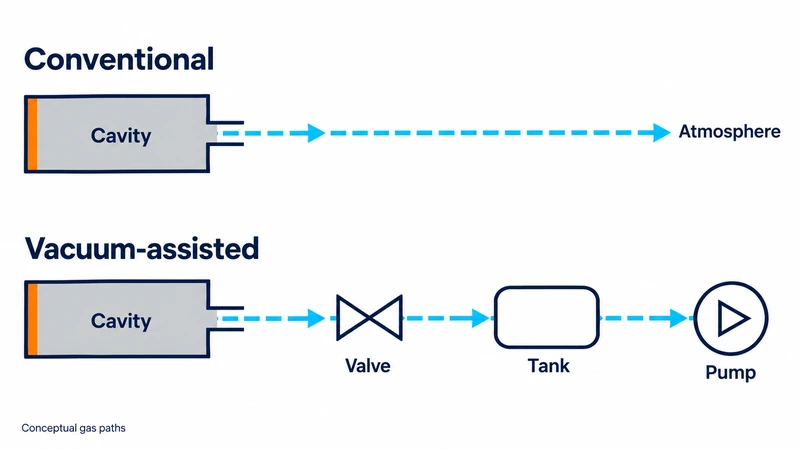
Conventional venting releases displaced gas toward the atmosphere through carefully sized passages. The vent land must pass gas while limiting metal escape; downstream relief channels must also offer sufficient capacity. A chill vent uses a path that promotes metal freezing while allowing gas discharge.
Vacuum assisted venting actively lowers pressure before and during the available evacuation period. It may be appropriate for demanding internal quality or thin wall applications. The die, evacuation channels, valve response, reservoir, pump, and shot timing must operate as one system.
The choice should follow the required part performance and the available evacuation window. Conventional venting may be adequate for one component, while another needs vacuum to meet internal quality targets. Request evidence for the proposed approach rather than selecting equipment solely from a headline vacuum rating.
Vacuum is not a substitute for a poor filling layout. Leaks, obstructed passages, or early valve closure can prevent the intended evacuation. Specify the measurement location and cycle timing: low reservoir pressure alone does not prove that the cavity reaches the required condition.
Designing an Effective Venting Path
Start with part geometry and the predicted flow pattern. Locate outlets where gas is expected to collect, and check whether metal can seal those outlets before neighboring regions finish filling. Several outlets may be needed when separate pockets form around complex cores.
Size the complete path for the gas volume and available evacuation time. Vent depth, width, land length, downstream restrictions, and contamination all affect performance. Select dimensions for the alloy, tooling, and process instead of applying a single universal vent depth or fixed gate to vent ratio.
Review accessibility with the intended maintenance team. A passage that cannot be cleaned consistently may lose capacity between scheduled services. Specify which inserts are replaceable and how wear or metal buildup will be assessed without enlarging the vent beyond its intended geometry.
Coordinate overflows with evacuation. An overflow may receive leading metal and help preserve a route toward a vent, but increasing its volume does not guarantee lower cavity pressure. Include practical access for cleaning and replacement, and account for trim removal and sealing around moving mold elements.
Common Venting Problems and What to Review
Use the following checks to guide investigation. Confirm the defect mechanism and compare results with the actual filling sequence before modifying the die.
| Observed problem | What to review |
| Gas pores near meeting fronts | Review gas isolation, gate direction, last fill locations, and vent closure timing. |
| Incomplete filling in remote sections | Check discharge restriction alongside die temperature, flow distance, and shot conditions. |
| Pores exposed after machining or leaks | Map defect location and connectivity; distinguish trapped gas from shrinkage before changing vents. |
| Unstable vacuum from shot to shot | Check seals, valve response, filters, piping restrictions, and the pressure measurement location. |
| Quality deteriorates during a run | Inspect deposits, blocked vent lands, worn seals, and changes in lubrication or thermal conditions. |
Validate and Maintain Venting Performance
Use filling simulation to compare metal arrival, merging fronts, and potential gas isolation. Review the assumptions for vent boundaries and vacuum conditions so a convenient model does not overstate evacuation. Where relevant, examine predicted air pressure together with fill time and temperature.
During trials, relate pressure traces and valve timing to shot position and metal arrival. Check relevant castings through radiography, sectioning, machining, or leak testing according to agreed acceptance criteria. A successful trial should demonstrate internal quality as well as complete external shape.
For an existing mold, establish a baseline before making changes. Compare suspect cavities, repeat the same inspection method, and track the defect rate by location. Changing vent geometry, lubrication, and injection settings simultaneously makes it harder to identify which correction actually improved the result.
Keep vent lands, chill blocks, filters, valves, and seals in the maintenance plan. Record cleaning intervals and changes in evacuation behavior. A gradual loss of performance can explain quality drift even when the nominal shot settings remain unchanged.
Plan Your HPDC Venting System with moldiecasting
At moldiecasting, we support custom die casting mold projects with DFM, gating and venting layout, cooling design, and mold flow analysis. Our mold design and engineering services connect part requirements with tooling decisions. Send your drawings, alloy, machine information, machining requirements, and quality targets through our contact us page
to discuss an HPDC venting system suited to your application.