

An HPDC gating system determines how molten metal reaches the die cavity and how the filling pattern develops. Poorly coordinated runners, gates, and overflows can contribute to cold shuts, trapped air, incomplete filling, and premature die wear. For buyers commissioning a die casting mold, understanding these features makes design reviews more useful and helps identify risks before steel is cut.
This guide focuses on cold chamber aluminum high pressure die casting. The same design questions apply to other HPDC applications, but dimensions and operating parameters must be adapted to the alloy, casting geometry, and machine.
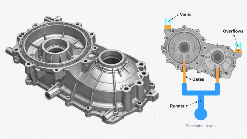
What an HPDC Gating System Includes
In a cold chamber machine, the plunger pushes metal from the shot sleeve through the runner system and inner gates into the cavity. Overflows receive metal leaving selected cavity locations, while connected vents or vacuum channels provide routes for gas removal. The biscuit is the solidified metal remaining at the shot sleeve end.
These elements work together. Runners distribute metal, inner gates establish its entry conditions, and overflows support the intended filling pattern. Venting must remain effective as filling progresses. Treating each feature as an isolated channel can create a layout that looks reasonable in CAD but performs poorly during production.
Runners Distribute and Direct Molten Metal
The main runner carries metal toward the casting, and branch runners divide the flow between gates or cavities. Their layout must deliver the required flow without excessive pressure loss, abrupt changes in direction, or poorly supplied branches. In a multicavity die, a visually symmetrical runner does not guarantee balanced filling when cavity volumes, gate restrictions, or temperatures differ.
Cross sections, bends, and junctions influence flow behavior. Smooth transitions and suitable radii help control disturbances, while the area of each branch should reflect the demand downstream. Fan and tangential arrangements offer different ways to spread or direct metal toward the gates; the choice depends on the available parting surface and desired entry pattern.
Oversizing runners adds metal that must be melted, trimmed, and returned to the process. Undersizing them can restrict flow. The objective is a runner network that supports filling within the machine capacity while keeping unnecessary shot weight under control.
Gates Control Entry into the Cavity
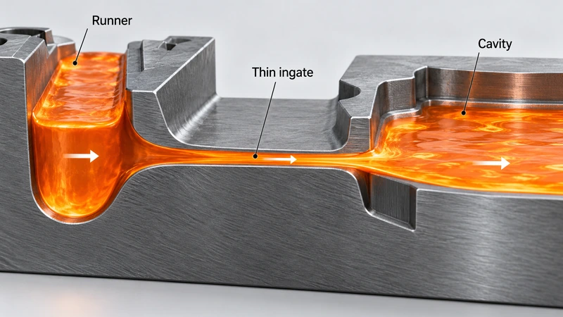
The inner gate connects the runner to the casting. Its position, direction, area, thickness, and width influence the speed and distribution of incoming metal. Gate placement should be considered alongside wall thickness, flow distance, ribs, holes, cores, and the locations where separate metal fronts will meet.
Directing a high velocity jet at a nearby core or die surface can increase local erosion risk. Multiple gates also require careful coordination: competing streams may trap gas or meet after losing too much heat. Gate locations must additionally allow practical trimming without unacceptable marks on functional or visible surfaces.
Initial sizing links the required filling volume, fill time, and average gate velocity. For a simplified estimate, flow rate Q equals volume V divided by fill time t, and total ingate area A equals Q divided by velocity v. Use consistent units and include overflow metal that passes through the ingates. Runner and biscuit volumes are excluded from this cavity filling calculation.
These relationships establish a starting point rather than a final specification. Gate thickness affects freezing, pressure transmission, and trimming; width affects how the flow spreads. Two gates with identical areas can therefore behave differently. Alloy properties, melt and die temperatures, and the machine pressure and flow capability must guide the final selection.
Overflows Support Filling and Work with Vents
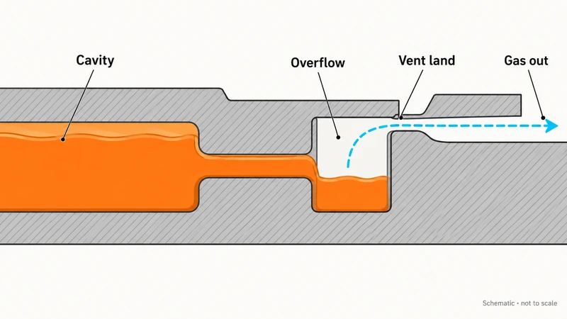
Overflows are pockets connected to selected regions of the casting. They can receive some of the cooler leading metal and oxide bearing material, help draw filling toward intended endpoints, and influence the local thermal condition. They are particularly relevant where flow must travel around cores or reach remote thin sections.
Their position should follow the expected filling sequence. Likely last fill regions and metal meeting points deserve attention, but the best location needs confirmation through simulation and trials. Overflow volume and connecting neck geometry also affect metal consumption, local heat, removal, and ejection.
An overflow is not a substitute for a vent. The pocket receives metal; the vent provides a path for gas to leave. If incoming metal closes that path too early, air may remain inside the cavity even when the overflow is large. Vacuum HPDC adds requirements for evacuation capacity, sealing, and valve timing that must be coordinated with filling.
Larger overflows do not automatically eliminate porosity. They cannot compensate for every unfavorable flow pattern, inadequate vent, or melt quality problem, and they should not be treated as conventional gravity casting risers.
A Practical Sequence for Gating System Design
Begin with the part requirements. Confirm the alloy, wall thickness distribution, critical dimensions, appearance, machining allowances, and leak tightness or mechanical performance targets. Review the parting line, cores, cooling, and ejection space before committing to gate locations. Explore our mold design and engineering services.
Next, establish a filling strategy. Decide where metal should enter, which regions it should reach first, where fronts may meet, and how gas will escape. Estimate fill time and ingate area, develop the runner branches, and position overflows and vents around that strategy.
Check the complete arrangement against the intended machine. Required flow must be achievable at the available pressure, with suitable plunger diameter, shot capacity, and injection settings. Locking force also needs assessment using projected area and the intended cavity pressure. Changing machines or plunger sizes can require revisiting the gating design.
Validate the Layout through Simulation and Trials
Filling simulation helps compare candidate layouts by showing flow progression, temperature changes, meeting fronts, and potential air entrapment. Solidification analysis helps locate hot spots and shrinkage risks. A published HPDC gate optimization study illustrates how CAE can support comparisons of runner, gate, and overflow arrangements.
Simulation results depend on their inputs, so confirm the design during die trials. Short shots can help reveal filling progression. Depending on the application, inspection may include radiography, sectioning, dimensional checks, or leak testing. Use the findings to adjust gating alongside cooling, venting, and shot settings.
Common Gating Problems and What to Review
Use the following checks during design reviews and trials. Confirm the defect mechanism before changing runner, gate, or overflow dimensions.
| Problem | What to review |
| Cold shuts or incomplete filling | Review flow distance, end of fill temperature, gate distribution, and actual fill time. Check melt and die temperatures. |
| Gas porosity or trapped air | Review merging fronts, last fill locations, blocked or prematurely sealed vents, and vacuum performance. |
| Erosion or soldering near the gate | Review jet direction, local velocity, core proximity, die temperature, and cooling. Check alloy and lubrication conditions. |
| Inconsistent quality between cavities | Compare branch flow, gate areas, filling sequence, and thermal conditions. Geometric symmetry alone does not establish balance. |
| Excessive return metal or trimming cost | Reassess runner and overflow volumes, gate removal access, and trim layout while preserving filling and venting performance. |
These symptoms can also reflect melt quality, spraying, thermal control, or equipment stability. Evaluate the gating system together with the process rather than assuming one dimensional change will resolve the defect.
Questions to Ask During a Mold Design Review
Ask the mold designer to explain the predicted last fill locations and show how the venting remains open until those regions fill. Request the assumptions behind the proposed gate area, including effective filling volume, target fill time, and machine capability. This turns a drawing review into a discussion of how the mold will actually run.
For parts with machined sealing faces or threaded holes, identify where internal defects would become unacceptable after machining. For visible parts, agree on allowable gate marks and overflow removal areas before tooling manufacture. These requirements can change the preferred filling direction even when another layout appears simpler to machine.
Plan Your HPDC Mold with moldiecasting
At moldiecasting, we provide custom die casting mold design for aluminum, zinc, and magnesium applications, supported by early DFM review and mold flow analysis. We evaluate gating alongside cooling and mold structure so the design reflects your part and production requirements. Share your 2D drawings, 3D model, alloy, machine specifications, and quality targets through our Contact Us page to discuss your HPDC gating system and mold project.